26
System Start-Up (Continued)
Low Ambient Damper Adjustment
(Factory or Field Installed)
When a unit is ordered with the low ambient option (i.e.,
Digit 11 is a “1” in the model number), a damper is factory
installed over the lead condenser fan for each refrigeration
circuit. Refer to the appropriate unit illustrated in Figure 5-1
for the damper locations.
For field installation, mount the dampers over the con-
denser fans at the locations shown in Figure 5-1 and con-
nect the actuator, controller, and sensor for each circuit.
(Refer to the Installation Instructions provided with each low
ambient damper kit.)
The controller has a factory default setpoint of 105
F. This
setpoint can be adjusted by installing a field supplied resis-
tor on 2TB34 in the low ambient control panel located in the
back of the main control panel. (See the low ambient wiring
diagram, that shipped with the unit or with the field kit, for
resistance values and installation location.)
Inspect the damper blades for proper alignment and opera-
tion. Dampers should be in the closed position during the
“Off” cycle. If adjustment is required;
1. Remove the sensor leads from the input terminals 6 and
7 for circuit #1 and/or 11 and 12 for circuit #2. (Controller
output signal will go to 0.0 VDC and the damper will drive
to the closed position.)
2. Loosen the damper shaft “Locking” set screws on the ac-
tuator
3. Firmly hold the damper blades in the closed position
4. Retighten the “Locking” set screws.
To check damper operation, jumper between the sensor in-
put terminals 6 and 7 and/or 11 and 12 (if applicable). Con-
troller output signal will go to 10 VDC and the damper will
drive to the full open position.
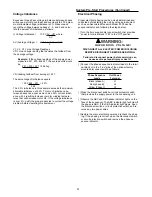
Charging the System
1. Verify that all discharge service valves and liquid line ser-
vice valves for each circuit is back seated.
2. Attach a set of service gauges onto the liquid line and
discharge line gauge ports for each circuit.
3. Charge liquid refrigerant into the liquid line of each refrig-
erant circuit with the required amount of R-22. Refriger-
ant should be charged into the system by weight.
Use an accurate scale or a charging cylinder to monitor
the amount of refrigerant entering the system. Refer to
Table 5-3 for the recommended refrigerant capacities for
the condensing unit. The weight of refrigerant required
for the liquid line and liquid line driers are listed in Table
5-4.
If the pressure within the system equalizes with the pres-
sure in the charging cylinder before charging is com-
pleted, complete the process by vapor charging into the
suction (low) side of the system after the system has
been started.
Table 5-2 gives the minimum starting temperatures for
both “Standard” & “Low” Ambient units.
Do not attempt to charge the system with the low ambi-
ent dampers and/or hot gas bypass operating (if appli-
cable). Disable the low ambient dampers in the “Open”
position (refer to the “Low Ambient Damper Adjustment”
section) and de-energize the hot gas bypass solenoid
valves before proceeding.
4. On units with dual circuits, start only one circuit at a time.
To disable the second circuit compressors, refer to the
compressor sequencing information that shipped with the
compressor unit.
5. With the compressors operating, slowly open the “Low
Side” valve on the manifold gauge set. The remainder of
the refrigerant will be drawn into the system.
6. Once the charging for the operating circuit has been
completed, check and record the:
ambient temperature;
compressor oil level (each circuit);
compressor suction and discharge pressures (each
circuit);
superheat and subcooling (each circuit);
Record this data on an “operator’s maintenance log” like the
one shown in Table 5-5. If the operating pressures indicate
a refrigerant shortage, measure the system superheat and
system subcooling. Repeat steps 1 through 6 for the sec-
ond refrigeration circuit, if applicable.
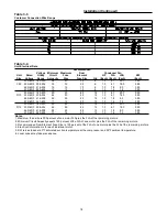
Table 5-2
Minimum Starting Ambient Temperatures
Standard Units
Low Ambient Units
Unit
With
No
With
No
Size
HGBP
HGBP
HGBP
HGBP
C80
D10
45
40
10
0
D12
Note:
Minimum starting ambients in degrees F, based
on unit at minimum step of unloading and 5 mph
wind across condenser.
Table 5-3
Recommended Refrigerant Capacities
Operating
Condenser
Unit
Charge per
Storage
Size
Circuit (1)
Capacity (2)
C80
52
136
D10
56
142
D12
74
184
Notes:
1. CAUC 80 - 120 are dual-circuit units
2. Pounds R-22 per circuit @ 95
o
F ambient,
95% full.
Summary of Contents for CAUC-C80
Page 8: ...8 Figure 3 2 CAUC C80 Unit Dimensional Data Recommended Clearances ...
Page 9: ...9 Figure 3 2 Continued CAUC D10 Unit Dimensional Data Recommended Clearances ...
Page 10: ...10 Figure 3 2 Continued CAUC D12 Unit Dimensional Data Recommended Clearances ...
Page 19: ...19 Installation Continued Figure 3 5 Typical CAUC C80 through D12 Field Wiring Diagram ...
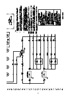
Page 28: ...28 Figure 5 2 Typical Wiring Schematic for 80 through 120 Ton Units ...
Page 29: ...29 ...
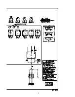
Page 30: ...30 Figure 5 3 Typical Control Panel Connections Diagram for 80 through 120 Ton Units ...
Page 31: ...31 ...
Page 36: ...36 ...


