24
System Start-Up
Sequence of Operation
Standard air cooled condensers function as the outdoor
condensing units for appropriately sized split refrigeration
systems. These units, operating in conjunction with a
matched indoor compressor/evaporator configuration, pro-
vide refrigerant condensing for these systems down to a
normal ambient temperature of 40
o
F. Operation to 0
o
F ambi-
ent is possible with the addition of externally mounted low
ambient dampers.
All condenser fans are direct drive, 26 inch propeller type.
They are driven by 1 HP thermally protected motors.
Condenser fan cycling is accomplished through interlocking
the fan operation with compressor operation (6K1 & 6K2),
and ambient temperature thermostats (1S42 & 1S43) are
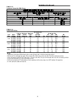
used to provide additional fan cycling control. Table 5-1 lists
the condenser fan sequencing data and Figure 5-1 illus-
trates the condenser fan locations with their respective fan
and relay designators.
When wired properly, the unit will start and operate satisfac-
torily as long as the operating temperature is above the
minimum operating temperature listed in Table 5-2.
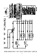
The condensing unit operation starts and stops automati-
cally when the cooling demand is initiated and terminated
by the cooling circuit interlock relays illustrated in
Figure 5-2.
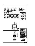
The control components are mounted in the various areas
of the unit as illustrated in Figure 5-3.
Table 5-1
Condenser Fan Sequencing Data
Controlling
Fan
Fan
Fan
Device
ON
OFF
Identification
Customer
Interlock
6K1
6K1
4B2, 4B5, 4B6 (1)
Circuit 1
Closed
Open
Customer
Interlock
6K2
6K2
5B2, 5B5, 5B6 (1)
Circuit 2
Closed
Open
Fan
Stage 1
Temperature
53
o
F
45
o
F
4B3 (1)
Switch
Stage 2
1S42 (2)
73
o
F
65
o
F
4B1, 4B4 (1)
Fan
Stage 1
Temperature
53
o
F
45
o
F
5B3
(1)
Switch
Stage 2
1S43 (2)
73
o
F
65
o
F
5B1, 5B4
Notes:
1. Bold fan identifies fans used on CAUC-D10 & D12 units
only.
2. 1S42 and 1S43 normally-closed contacts open on
ambient temperature drop to "OFF" setpoints.
Contacts reclose on ambient temperature rise
on "ON" setpoints.
Low Ambient Damper Operation
Low Ambient Dampers are available as a factory installed
option or can be field-installed. Dampers are used to extend
the operation of these units from the standard operational
temperatures to a minimum of 0
o
F without hot gas bypass
or 10
o
F with hot gas bypass. (These values apply when
wind speed across the condenser coil is less than 5 m.p.h.).
If typical wind speeds are higher than 5 m.p.h., a wind
screen around the unit may be required. By restricting the
airflow across the condenser coils, saturated condensing
temperatures can be maintained as the ambient tempera-
tures change.
The low ambient damper actuator controls damper modula-
tion for each refrigerant circuit in response to saturated con-
densing temperature.
Low Ambient Thermostat Operation
In addition to the low ambient dampers a two stage low am-
bient thermostat is installed to further restrict the airflow
across the condenser by cycling the 4B1 + 4B6, 5B1 + 5B6
on 100 & 120 Ton units. The final stage thermostats opens
when the ambient temperature approaches 65
o
F and closes
at approximately 73
o
F. The second stage opens when the
ambient temperature approaches 45
o
F and closes at ap-
proximately 53
o
F.
Summary of Contents for CAUC-C80
Page 8: ...8 Figure 3 2 CAUC C80 Unit Dimensional Data Recommended Clearances ...
Page 9: ...9 Figure 3 2 Continued CAUC D10 Unit Dimensional Data Recommended Clearances ...
Page 10: ...10 Figure 3 2 Continued CAUC D12 Unit Dimensional Data Recommended Clearances ...
Page 19: ...19 Installation Continued Figure 3 5 Typical CAUC C80 through D12 Field Wiring Diagram ...
Page 28: ...28 Figure 5 2 Typical Wiring Schematic for 80 through 120 Ton Units ...
Page 29: ...29 ...
Page 30: ...30 Figure 5 3 Typical Control Panel Connections Diagram for 80 through 120 Ton Units ...
Page 31: ...31 ...
Page 36: ...36 ...


