


23
System Pre-Start Procedures (Continued)
Voltage Imbalance
Excessive three phase voltage imbalance between phases
will cause motors to overheat and eventually fail. The maxi-
mum allowable voltage imbalance is 2%. Measure and
record the voltage between phases 1, 2, and 3 and calcu-
late the amount of imbalance as follows:
% Voltage Imbalance =
100 X
AV - VD
where;
AV
AV (Average Voltage) =
Volt 1 + Volt 2 + Volt 3
3
V1, V2, V3 = Line Voltage Readings
VD = Line Voltage reading that deviates the farthest from
the average voltage.
Example: If the voltage readings of the supply power
measured 221, 230, and 227, the average volts would
be:
221 + 230 + 227 = 226 Avg.
3
VD (reading farthest from average) = 221
The percentage of Imbalance equals:
100 X 226 - 221 = 2.2%
226
The 2.2% imbalance in this example exceeds the maximum
allowable imbalance of 2.0%. This much imbalance be-
tween phases can equal as much as a 20% current imbal-
ance with a resulting increase in motor winding tempera-
tures that will decrease motor life. If the voltage imbalance
is over 2%, notify the proper agencies to correct the voltage
problem before operating this equipment.
Electrical Phasing
Proper electrical phasing can be quickly determined and
corrected before starting the unit by using an instrument
such as an Associated Research Model 45 Phase Se-
quence Indicator and following the steps below:
[ ] Turn the field supplied disconnect switch that provides
power to terminal block 1TB1 to the "Off" position.
H A Z A R D O U S V O LTA G E !
DISCONNECT ALL ELECTRIC POWER INCLUDING
REMOTE DISCONNECTS BEFORE SERVICING.
Failure to disconnect power before servicing can
cause severe personal injury or death.
[ ] Connect the phase sequence indicator leads to the termi-
nal block or to the "Line" side of the optional factory
mounted disconnect switch as follows;
Phase Sequence
Unit Power
Leads
Terminal
Black (phase A)
L1
Red (phase B)
L2
Yellow (Phase C)
L3
[ ] Close the disconnect switch or circuit protector switch
that provides the supply power to the condensing unit.
[ ] Observe the ABC and CBA phase indicator lights on the
face of the sequencer. The ABC indicator light will glow if
the phase is ABC. If the CBA indicator light glows, open
the disconnect switch or circuit protection switch and re-
verse any two power wires.
[ ] Restore the main electrical power and recheck the phas-
ing. If the phasing is correct, open the disconnect switch
or circuit protection switch and remove the phase se-
quence indicator.
Summary of Contents for CAUC-C80
Page 8: ...8 Figure 3 2 CAUC C80 Unit Dimensional Data Recommended Clearances ...
Page 9: ...9 Figure 3 2 Continued CAUC D10 Unit Dimensional Data Recommended Clearances ...
Page 10: ...10 Figure 3 2 Continued CAUC D12 Unit Dimensional Data Recommended Clearances ...
Page 19: ...19 Installation Continued Figure 3 5 Typical CAUC C80 through D12 Field Wiring Diagram ...
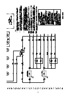
Page 28: ...28 Figure 5 2 Typical Wiring Schematic for 80 through 120 Ton Units ...
Page 29: ...29 ...
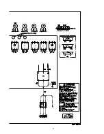
Page 30: ...30 Figure 5 3 Typical Control Panel Connections Diagram for 80 through 120 Ton Units ...
Page 31: ...31 ...
Page 36: ...36 ...


