Trane ADD1B060A9H31B Installer'S Manual Download Page 3

Installer’s Guide

18-CD21D1-12  

3

Installation Instructions 

3

General Installation Instructions 

4

Location and Clearances 

4

Outline Drawing 

5

Upflow Installation 

7

Downflow Installation 

7

Air For Combustion and Ventilation 

8

Duct Connections 

10

Return Air Filters 

11

Typical Upflow Return Air Filter Installations 

11

Alternate Upflow Filter Clip / Bracket Installation  

13

Typical Downflow Furnace Return Air Filter Installations 

13

General Venting Instructions 

14

Venting Into a Masonry Chimney 

15

Electrical Connections 

16

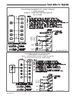
Field Wiring Diagrams 

17

Gas Piping 

19

Sequence of Operation 

19

Start Up and Adjustment 

20

Preliminary Inspections 

20

Combustion and Input Check 

20

High Altitude Derate 

21

Lighting Instructions 

22

Control and Safety Switch Adjustment 

23

Abnormal Conditions 

23

IFC Error Flash Codes 

24

Contents

WARNING

!

FIRE OR EXPLOSION HAZARD

Failure to follow the safety warnings exactly could 

result in serious injury, death or property damage. 

Improper servicing could result in dangerous opera-

tion, serious injury, death, or property damage.

Safety signal words are used to designate a degree 
or level of seriousness associated with a particular 
hazard.  The signal words for safety markings are 

WARNING

, and 

CAUTION

.

 a. 

WARNING

 indicates a potentially hazardous situa-

tion which, if not avoided, could result in death or 
serious injury.

 b. 

CAUTION

 indicates a potentially hazardous situa-

tion which, if not avoided, may result in minor or 
moderate injury. It is also used to alert against un-
safe practices and hazards involving only property 
damage.

CAUTION

!

T

o prevent shortening its service life, the furnace 

should not be used as a “Construction Heater” during 

the finishing phases of construction until the require-

ments listed in item 9, a-g of the safety section of this 

publication have been met.   Condensate in the pres-

ence of chlorides and fluorides from paint, varnish, 

stains, adhesives, cleaning compounds, and cement 

create a corrosive condition which may cause rapid de-

terioration of the heat exchanger.

WARNING

!

These furnaces are not approved or intended for instal-

lation in manufactured (mobile) housing, trailers, or 

recreational vehicles. 

Failure to follow this warning could result in property 

damage, personal injury, or death.

CAUTION

!

Do  NOT install the furnace in a corrosive or contami-

nated atmosphere.

Summary of Contents for ADD1B060A9H31B

Page 1: ...with this unit Please return to service information pack upon completion of work Installer s Guide UD1B100A9H31B UD1B100G9H31A UD1C100A9H51B UD1C100G9H51A UD1D120A9H51B UD1D120G9H51A UD1D140A9H51B UD1...

Page 2: ...ate mark ing e 100 of the furnace combustion air requirement must come from outside the structure SAFETY SECTION CARBON MONOXIDE POISONING HAZARD Failure to follow the steps outlined below for each ap...

Page 3: ...ty signal words are used to designate a degree or level of seriousness associated with a particular hazard The signal words for safety markings are WARNING and CAUTION a WARNING indicates a potentiall...

Page 4: ...avoid physical damage from vehicles GENERAL INSTALLATION INSTRUCTIONS The manufacturer assumes no responsibility for equip ment installed in violation of any code or regulation It is recommended that...

Page 5: ...D TUD1A040A9H21B TUD1A040G9H21A 14 1 2 9 5 8 13 1 4 13 TUD1B060A9H31B TUD1B060G9H31A TUD1B080A9H31B TUD1B080G9H31A TUD1B100A9H31B TUD1B100G9H31A 17 1 2 9 5 8 16 1 4 16 TUD1C080A9H41B TUD1C080G9H41A T...

Page 6: ...6 18 CD21D1 12 Installer s Guide From Dwg 21C341700 Sh 1 Rev 0 DD1 HF OUTLINE DRAWING ALL DIMENSIONS ARE IN INCHES...

Page 7: ...coil in the horizontal posi tion See Figure 4 IMPORTANT The 2 4TXC cased coil must be placed downstream of the furnace In horizontal installations the apex of the coil may point either toward or away...

Page 8: ...ir open ings provided in the furnace casing must be kept free of obstructions which restrict the flow of air Airflow restrictions affect the efficiency and safe operation of the furnace Keep this in m...

Page 9: ...rcial buildings Buildings with indoor pools Furnaces installed in commercial laundry rooms Furnaces installed in hobby or craft rooms Furnaces installed near chemical storage areas Exposure to the fol...

Page 10: ...the space containing the furnace Minimum return air entering temperature for the furnace is 55 F Where there is no complete return duct system the re turn connection must be run full size from the fur...

Page 11: ...Thin cloths should be placed over the registers and the furnace fan should be run for 10 minutes Don t forget to remove the cloths be fore you start the furnace FILTER REMOVE FILTER FROM UPFLOW FURNAC...

Page 12: ...ACK960 The following checklist should be used when installing a right or left side return filter on an upflow furnace a Remove the filter b Leave the bottom panel in place c Make side cutout by follow...

Page 13: ...stream of the fur nace See Figure 17 UPFLOW FILTER CLIP BRACKET INSTALLATION 1 Determine the location to be used The furnace cabinet has dimples for location of the alter nate furnace clips Side retur...

Page 14: ...4 or the CAN CGA B149 Installation Codes and these instructions Determine that there is no blockage or restriction leakage corrosion and other deficiencies which could cause an unsafe condition 3 As f...

Page 15: ...isions of ANSI Z21 47 and CAN CGA 2 3 standards Category I furnaces operate with a non positive vent static pressure and with a flue loss of not less than 17 percent NOTE If desired a side wall termin...

Page 16: ...ATIONS d ELECTRICAL CONNECTIONS WARNING The cabinet must have an uninterrupted or unbroken ground according to National Electrical Code ANSI NFPA 70 latest edition and Canadian Electrical Code CSA C22...

Page 17: ...SING A 1 STAGE HEATING THERMOSTAT NO COOLING From Dwg 21B341437 P01 OUTDOOR UNIT NO TRANSFORMER SEE NOTE 6 From Dwg B341436 Rev 1 SEE NOTE 8 FURNACE TWIN SEE NOTE 7 B C B C TO 115 V 1 PH 60 HZ POWER S...

Page 18: ...PERATION OF UNIT NO 2 IS SYNCRONIZED WITH UNIT NO 1 VIA SIGNALS FROM TWIN CONNECTION SEE NOTE 4 SEE NOTE 3 ISOLATION RELAY FIELD SUPPLIED SEE NOTE 4 ISOLATION RELAY SEE NOTE 4 B C B C B C From Dwg 21B...

Page 19: ...g by closing its individual manual shut off valve dur ing any pressure testing of the gas supply piping sys tem at test pressures equal to or less than 1 2 psig CAUTION Use a backup wrench on the gas...

Page 20: ...from the utility company and compare to the nameplate rating This must not exceed the nameplate rating Gas Valve Adjustment Changes can be made by adjusting the manifold pres sure See Table 12 or cha...

Page 21: ...the heating value obtained from the local utility supplier for the gas being delivered at the in stalled altitude Input rate changes can be made by adjusting the manifold pressure min 3 0 max 3 7 in...

Page 22: ...is satisfied TO SHUT OFF For complete shutdown Move the control switch on the main gas valve to the OFF position See Figures 25 and 26 Disconnect the electrical supply to the unit CAUTION If this is d...

Page 23: ...CONTROL AND SAFETY SWITCH ADJUSTMENT LIMIT SWITCH CHECK OUT The limit switch is a safety device designed to close the gas valve should the furnace become overheated Since proper operation of this swit...

Page 24: ...g cycle the pressure switch will cause the gas valve to close and shut the unit down Carbon monoxide fire or smoke can cause serious bodi ly injury death and or property damage A variety of potential...

Reviews: