


Installer’s Guide
18-CD21D1-12
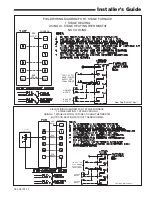
TABLE 7
MASONRY CHIMNEY VENTING
Type Furnace
Tile Lined Chimney
Chimney Lining
Internal
External
“B” Vent
Flexible
Metal Liner
Single Fan
Assist
No
No
Yes
Yes*
Fan Assist
+
Fan Assist
No
No
Yes
Yes*
Fan Assist
+
Natural
Yes
No
Yes
Yes*
* Flexible chimney liner size is determined by using the type “B” vent size
for the available BTUH input, then reducing the maximum capacity by 20%
(multiply maximum capacity times 0.80). The minimum capacity is the same
as shown in the “B” vent tables.
External Masonry Chimney
Venting of fan assisted appliances into external chim-
neys (one or more walls exposed to outdoor tempera-
tures), requires the chimney be lined with type “B”,
double wall vent or suitable flexible chimney liner
material. This applies in all combinations of common
venting as well as for fan assisted appliances vented
alone.
▲
WARNING
!
CARBON MONOXIDE POISONING HAZARD
Failure to follow the installation instructions for the
venting system being placed into operation could re-
sult in carbon monoxide poisoning or death.
The following installation practices are recommended
to minimize corrosion caused by condensation of flue
products in the furnace and flue gas system.
1. Avoid an excessive number of bends.
2. Horizontal runs should pitch upward at least 1/4"
per foot.
3. Horizontal runs should be as short as possible.
4. All vent pipe or connectors should be securely sup-
ported and must be inserted into, but not beyond
the inside wall at the chimney vent.
5. When vent connections must pass through walls or
partitions of combustible material, a thimble must
be used and installed according to local codes.
6. Vent pipe through the roof should be extended to
a height determined by National Fuel Gas Code or
local codes. It should be capped properly to prevent
rain water from entering the vent. Roof exit should
be waterproofed.
7. Use type “B” double wall vent when vent pipe is
routed through cool spaces (below 60° F.).
VENT PIPING
These furnaces have been classified as Fan-Assisted
Combustion System, Category I furnaces under the
“latest edition” provisions of ANSI Z21.47 and CAN/
CGA 2.3 standards. Category I furnaces operate with a
non-positive vent static pressure and with a flue loss of
not less than 17 percent.
NOTE:
If desired, a side wall termination can be accomplished
through the use of an “add-on” draft inducer. The in-
ducer must be installed according to the inducer man-
ufacturer’s instructions. Set the barometric pressure
relief to achieve -0.02 inch water column.
NOTE: When the downflow furnace is vented through
the left side of the furnace cabinet using the provided
cutout, Type B vent piping must be used.
The furnace shall be connected to a factory built chim-
ney or vent complying with a recognized standard, or a
masonry or concrete chimney lined with a lining mate-
rial acceptable to the authority having jurisdiction.
▲
WARNING
!
Furnace venting into an unlined masonry chimney or
concrete chimney is prohibited.
Failure to follow this warning could result in property
damage, personal injury, or death.
VENTING INTO A MASONRY CHIMNEY
If the chimney is oversized, the liner is inadequate, or
flue-gas condensation is a problem in your area, con-
sider using the chimney as a pathway or chase for type
“B” vent or flexible vent liner. If flexible liner material
is used, size the vent using the “B” vent tables, then
reduce the maximum capacity by 20% (multiply 0.80
times the maximum capacity). Masonry Chimney Kit
BAYVENT800B may be used with these furnaces
(Up-
flow model furnaces only)
to allow venting into a
masonry chimney. Refer to the BAYVENT800B Install
-
er’s Guide for application requirements.
INTERNAL MASONRY CHIMNEYS
Venting of fan assisted appliances into a lined, inter-
nal masonry chimney is allowed only if it is common
vented with at least one natural draft appliance;
OR
,
if the chimney is lined with type “B”, double wall vent
or suitable flexible liner material (See Table 7).
▲
WARNING
!
The chimney liner must be thoroughly inspected to
insure no cracks or other potential areas for flue gas
leaks are present in the liner. Liner leaks will result in
early deterioration of the chimney.
Failure to follow this warning could result in carbon
monoxide poisoning or death.
NOTE:
The following section does not apply if BAYVENT800B
(Masonry Chimney Vent Kit) is used. All instructions
with the kit must be followed.


