Trane 4TTM3018 Installer'S Manual Download Page 25

18-AC78D1-6 


 25 

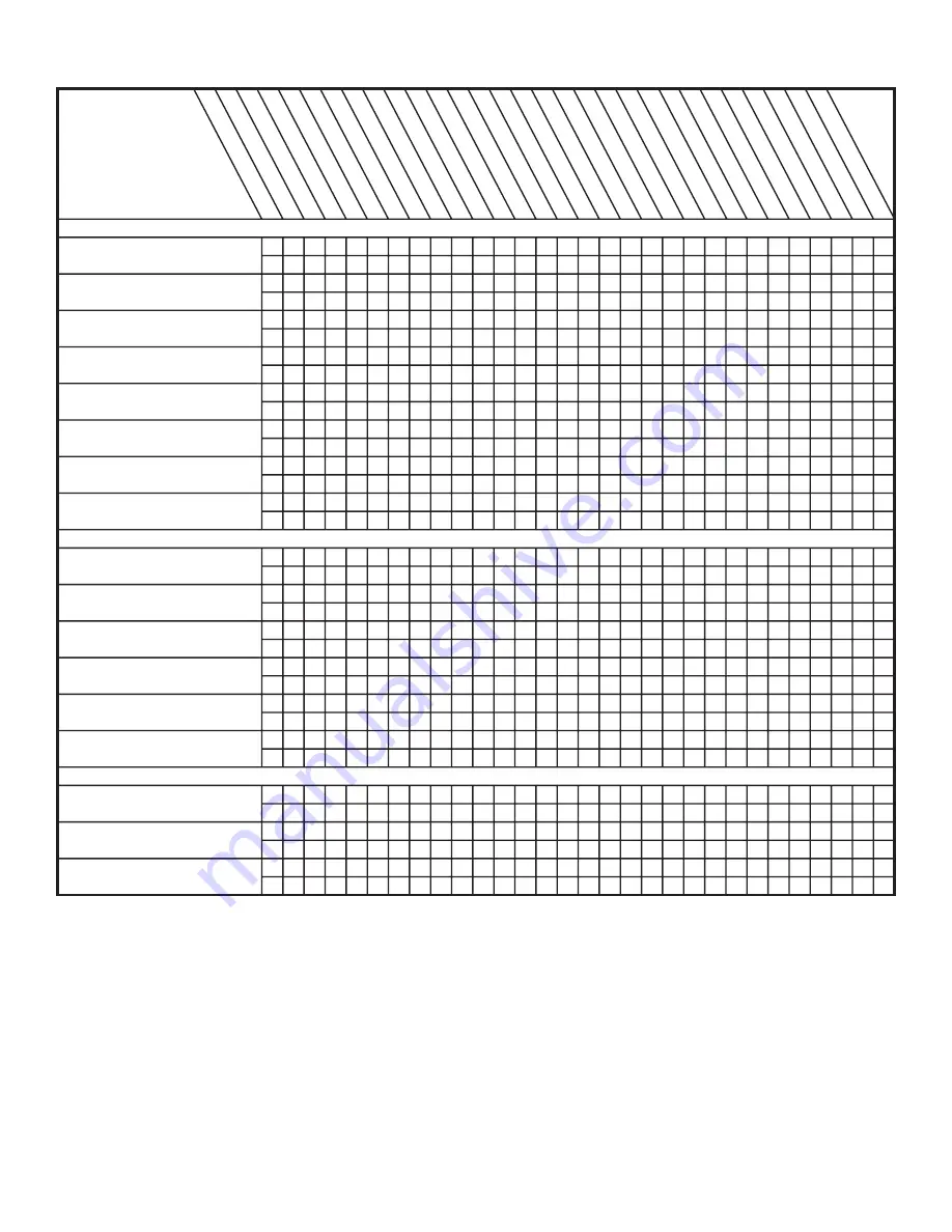
15.2 Troubleshooting

SYSTEM FAULTS

REFRIGERANT  CIRCUIT

Head  Pressure  Too  High

Head  Pressure  Too  Low

Suction  Pressure  Too  High

Suction  Pressure  Too  Low

Liquid  Refrig.  Floodback  (TXV/EEV)

Liquid  Refrig.  Floodback

(Cap. Tube)

I.D.  Coil  Frosting

Compressor  Runs

Inadequate  or  No  Cooling/Htg
ELECTRICAL
Compressor  &  O.D.  Fan

Won’t  Start
Compressor  Will  Not  Start

But  O.D.  Fan  Runs

O.D.  Fan  Won’t  Start

Compressor  Hums  But  Won’t  Start

Compressor  Cycles  on  IOL

I.D.  Blower  Won’t  Start

DEFROST

Unit  Won’t  Initiate  Defrost

Defrost  Terminates  on  Time

Unit  Icing  Up

W

HA

T T

CH

EC

K M

OD

E

PO

W

ER

 S

UP

PLY

HIG

H V

OLT

AG

E W

IRIN

G

CO

MP

RE

SS

OR

 IO

L

RU

N C

APA

CIT

OR

STA

RT

 C

APA

CIT

OR

STA

RT

 R

EL

AY

CO

NTA

CT

OR

 C

ON

TAC

TS

LO

W

 VO

LTA

GE

 W

IRIN

G

CO

NT

RO

L T

RA

NS

FO

RM

ER

TH

ER

MO

STA

T

CO

NTA

CT

OR

 C

OIL

LO

W

 VO

LTA

GE

 FU

SE

ST

UC

K C

OM

PR

ES

SO

R

INE

FF

ICIE

NT

 C

OM

P.

RE

F. U

ND

ER

CH

AR

GE

RE

F. O

VE

RC

HA

RG

E

EX

CE

SS

IVE

 E

VA

P. L

OA

D

NO

NC

ON

DE

NS

AB

LE

S

RE

S. 

O.D

. A

IRF

LO

W

O.D

. A

IR 

RE

CIR

CU

LAT

IO

N

TX

V/E

EV

 S

TU

CK

 O

PE

N

SU

PE

RH

EAT

RE

S. 

I.D

. A

IRF

LO

W

RE

F. C

IR. 

RE

ST

RIC

TIO

NS

SO

V L

EA

KIN

G

SO

V C

OIL

 D

EF

EC

TIV

E

CH

EC

K V

ALV

E L

EA

KIN

G

*

DE

FR

OS

T R

EL

AY

 D

EF.

DE

FR

OS

T C

ON

TR

OL

 D

EF.

C
H
C
H
C
H
C
H
C
H
C
H
C
H
C
H

C
H
C
H
C
H
C
H
C
H
C
H

C
H
C
H
C
H

P
P

P
P

P
P
P
P
P
P

P
P
P
P

S
S

S
S

S
S

S
S
S
S

S
S

S
S
S
S

S
S
S
S
S
S
S
S

S
S

S
S

P
P

P
P

S
S

S
S

P
P

P
P

S
S

P
P

P
P
P
P

P
P
P
P
P
P
P
P

S
S
S
S

S
S

S
S

P
P

P
P

P

P
P

P
P

P

P

P
P

P

P
P

P
P

P
P

P

S

S
S

S
S

S
S

P

S

S
S
S

S
S

S

S

S

S
S
S

S

S

S
S

P
P

S
S
S
S
S
S

S
S

S
S

S
S

P

P

P

P
P

P

S

S
S
S
S

S
S

S
S

S
S
P
P

S
S

S
S

S

S

S

S

P

P

P
P
P

P
P

S
S

P P

P

P

C  -  Cooling      H  -  Heating      P  -  Primary  Causes      S  -  Secondary  Causes     

*

  -  3  Phase  Only

Summary of Contents for 4TTM3018

Page 1: ...oor systems All of the manufac turer s split systems are A H R I rated only with TXV indoor systems Some of the benefits of installing approved matched indoor and outdoor split systems are maximum efficiency optimum performance and the best overall system reliability 4TTM3018 through 4TTM3060 Installer s Guide Table of Contents Section 1 Safety 2 Section 2 Unit Location Considerations 3 Section 3 ...

Page 2: ...e system for component replacement For specific handling concerns with R 410A and POE oil reference Retrofit Bulletin SSC APG011 EN WARNING UNIT CONTAINS R 410A REFRIGERANT R 410A operating pressures exceed the limit of R 22 Proper service equipment is required Failure to use proper service tools may result in equipment damage or personal injury SERVICE USE ONLY R 410A REFRIGERANT AND AP PROVED PO...

Page 3: ... 60 feet Compressor crankcase heat is required for line lengths over 60 feet Use only the line diameters indicated in Table 5 1 Section 2 Unit Location Considerations 2 1 Unit Dimensions and Weight 2 2 Refrigerant Piping Limits D H W Unit Dimensions and Weight Models H x D x W Weight 4TTM3018 036 28 7 8 x 23 1 2 x 25 1 2 154 4TTM3042 060 28 7 8 x 28 1 2 x 29 1 4 168 Weight values are estimated Sta...

Page 4: ...ce must be provided in front of the control box access panels and any other side requiring service Do not locate close to bedrooms operational sounds may be objectionable Min 12 to Shrubbery Position the outdoor unit a minimum of 12 from any wall or surrounding shrubbery to ensure adequate airflow Outdoor unit location must be far enough away from any structure to prevent excess roof runoff water ...

Page 5: ...re the refrigerant charge has been retained during shipment Section 4 Setting the Unit 4 1 Pad Installation When installing the unit on a support pad such as a concrete slab consider the following The pad should be at least 1 2 larger than the unit on all sides The pad must be separate from any structure The pad must be level The pad should be high enough above grade to allow for drainage The pad ...

Page 6: ... Vapor Line Connection Liquid Line Connection 4TTM3018A 5 8 3 8 5 8 3 8 4TTM3024A 5 8 3 8 5 8 3 8 4TTM3030A 3 4 3 8 3 4 3 8 4TTM3036A 3 4 3 8 3 4 3 8 4TTM3042A 7 8 3 8 7 8 3 8 4TTM3048A 7 8 3 8 7 8 3 8 4TTM3060A 7 8 3 8 7 8 3 8 Table 5 1 Line Length Or 5 3 Refrigerant Line Insulation Important The Vapor Line must always be insulated DO NOT allow the Liquid Line and Vapor Line to come in direct met...

Page 7: ... a structure use isolation type hangers Isolation hangers should also be used when refrigerant lines are run in stud spaces or enclosed ceilings Where the refrigerant lines run through a wall or sill they should be insulated and isolated Isolate the lines from all ductwork Minimize the number of 90º turns Comply with National State and Local Codes when isolating line sets from joists rafters walls...

Page 8: ... or other appropriate method every 8 ft 8 Feet Maximum Isolation Through Wall DO NOT hang line sets from ductwork Sealant Insulation Vapor Line Wall Ductwork Isolator Line Set Section 7 Refrigerant Line Brazing 7 1 Braze The Refrigerant Lines STEP 1 Remove caps or plugs Use a deburing tool to debur the pipe ends Clean both internal and external surfaces of the tubing using an emery cloth ...

Page 9: ...e the refrigerant lines to the service valves Check liquid line filter drier s directional flow arrow to confirm correct direction of refrigeration flow away from outdoor unit and toward evaporator coil as il lustrated Braze the filter drier to the Liquid Line Continue the dry nitrogen purge Do not remove the wet rag until all brazing is completed Important Remove the wet rag before stopping the d...

Page 10: ... the service valves have cooled STEP 2 Check for leaks by using a soapy solution or bubbles at each brazed location Section 8 Refrigerant Line Leak Check 8 1 Check For Leaks STEP 1 Pressurize the refrigerant lines and evapo rator coil to 150 PSIG using dry nitrogen 150 PSIG ...

Page 11: ... the service valves Important The Vapor Service Valve must be opened first BEFORE opening the Liquid Service Valve STEP 1 Remove service valve cap STEP 2 Fully insert 3 16 hex wrench into the stem and back out counterclockwise until valve stem just touches the rolled edge approximately five 5 turns STEP 3 Replace the valve stem cap to prevent leaks Tighten finger tight plus an additional 1 6 turn ...

Page 12: ...low Green White Blue B B B Blue Blue W W1 W2 W3 G G Y Y Yellow Yellow Low Voltage connection must be made inside the outdoor unit case R R Red Comfort Control Air Handler Air Conditioner Factory wiring Variable Speed Air Handler Hook up Diagram Red Yellow Green White Blue Yellow Green White Blue B B Blue Blue W G Y Y Yellow Yellow Low Voltage connection must be made inside the outdoor unit case R ...

Page 13: ... Yellow B Y Yellow Low Voltage connection must be made inside the outdoor unit case R Red Yellow Green White Black Blue R Red W2 is present only on 2 stage comfort control and furnace Factory wiring Comfort Control 1 or 2 Stage Gas Furnace Air Conditioner Variable Speed Gas Furnace Hook up Diagram Red Yellow Green White Black Blue Yellow Green White Black W2 W2 is present only on 2 stage comfort c...

Page 14: ...gh Voltage Disconnect Switch 12 3 High Voltage Ground Ground the outdoor unit per national state and local code requirements Install a separate disconnect switch at the outdoor unit Field provided flexible electrical conduit must be used for high voltage wiring LIVE ELECTRICAL COMPONENTS During installation testing servicing and trouble shooting of this product it may be necessary to work with liv...

Page 15: ...EL ON OFF STEP 4 Wait five 5 minutes before moving to Step 5 if no crankcase heater accessory is used Wait one 1 hour before starting the unit if compres sor crankcase heater accessory is used and the Outdoor Ambient is below 70ºF 60 MIN STEP 1 Ensure Sections 7 8 9 10 11 12 and 13 have been completed DONE CANCEL TUE PM SYSTEM EM HEAT OFF COOL CHANGE FILTER UV LAMP HUMIDIFIER PAD Following Schedul...

Page 16: ...n completed STEP 3 Stabilize the system Operate the system in cooling mode for a minimum of ten 10 minutes Important Whenever charge is removed or add ed the system must be operated for a minimum of ten 10 minutes to stabilize before accurate measurements can be made If Suction Line Pressure is below 115 PSIG the sys tem may experience fluctuations in pressures and temperatures due to expansion va...

Page 17: ... out door unit model number 2 Find the Measured Outdoor Ambient Temperature along the top of the chart For this example the Measured Outdoor Ambient Temperature is 97 ºF 3 Locate the Measured Suction Pressure along the left side of the chart For this example the Measured Suction Pressure is 130 PSIG 4 Determine the Target MINIMUM Liquid Temperature at the intersection of the Mea sured Suction Pres...

Page 18: ...e hunting If fluctuations in Suction Line Pressure are noted then use the average PSIG STEP 4 Measure Outdoor Ambient air temperature entering coil Outdoor Ambient air temperature ________ F 6 Manual Charge Assist Hookup Leave bottle closed until ready to charge STEP 6 Determine the Liquid Line Temperature Attach a K type temperature probe to the Liquid Line close to the Liquid Line Service Valve ...

Page 19: ... 115 use the 115 pressure on the table 4 Determine the Target MINIMUM Liquid Temperature at the intersection of the Measured Suction Pressure and the Measured Outdoor Ambient Temperature If intersection falls between two listed temperatures on the table you will need to estimate 5 Locate the Maximum Allowable Liquid Pressure along the bottom of the table If intersection falls between two listed pr...

Page 20: ...20 18 AC78D1 6 4TTM3018A1 4TTM3024A1 4TTM3030A1 4TTM3036A1 Charging Tables ...

Page 21: ...18 AC78D1 6 21 4TTM3048A1 4TTM3042A1 4TTM3060A1 ...

Page 22: ...e Required Refrigerant Adjustment Compare the Measured Liquid Line Temperature from Step 6 against the Target MINIMUM Liquid Temperature from Step 7 If the Measured Liquid Line Temperature is above the Target MINIMUM Liquid Temperature and the Maximum Allowable Liquid Pressure has not been exceeded you will add charge to the system If the Measured Liquid Line Pressure is higher than the Maximum Al...

Page 23: ...essure mea sured in Step 5 repeat Steps 6 9 and locate the new Target MINIMUM Liquid Temperature and Maximum Allowable Liquid Pressure using the table Adjust charge if required 10 MIN STEP 11 Record System Information Record system pressures and temperatures after charging is complete Outdoor model number _________________ Measured Outdoor Ambient __________ ºF Measured Indoor Ambient __________ º...

Page 24: ...st the following list Final phases of this installation are the unit Operational and Checkout Procedures To obtain proper performance all units must be operated and charge adjustments made Important Perform a final unit inspection to be sure that factory tubing has not shifted during shipment Adjust tubing if necessary so tubes do not rub against each other when the unit runs Also be sure that wir...

Page 25: ...M O S T A T C O N T A C T O R C O I L L O W V O L T A G E F U S E S T U C K C O M P R E S S O R I N E F F I C I E N T C O M P R E F U N D E R C H A R G E R E F O V E R C H A R G E E X C E S S I V E E V A P L O A D N O N C O N D E N S A B L E S R E S O D A I R F L O W O D A I R R E C I R C U L A T I O N T X V E E V S T U C K O P E N S U P E R H E A T R E S I D A I R F L O W R E F C I R R E S T R I ...

Page 26: ...s If Suction Line Pressure is below 115 PSIG the system may experience fluctuations in pressures and temperatures and test results may not be accurate When system is stabilized measure Suction Line Pressure and enter the result on LINE 2 of the Charge Verification Worksheet STEP 3 With the system still stabalized measure the Liquid Line Pressure and record the result on LINE 3 of the Charge Verifi...

Page 27: ... from line 6 Liquid Line Temp Target ____________F from line 5 LINE 8 Target Subcooling ____________F CALCULATE SUBCOOLING DIFFERENCE Actual Subcooling ____________ F from line 7 Target Subcooling ____________ F from line 8 Subcooling Difference _____________ F If the Subcooling Difference is within the tolerance range the system has passed the Charge Verification If Subcooling Difference is NOT w...

Page 28: ... and product data improvement and it reserves the right to change design and specifications without notice Trane U S Inc 2012 Representative only illustrations included in this document 6200 Troup Highway Tyler TX 75707 www trane com www americanstandardair com 04 12 ...

Reviews: