Page 14
Installer’s Guide
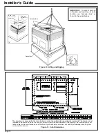
Figure 10. Lifting and Rigging
This drawing was prepared by the manufacturer in order to provide detail regarding job layout only. This drawing is not
intended to be used as a basis to construct, build or modify the item depicted in the drawing. The manufacturer is not
responsible for the unauthorized use of this drawing and expressly disclaims any liability for damages resulting from
such unauthorized use.
Gasket Seal
Spreader Bars
Base of unit
rest on top of
curb rails
Drip lip on
perimeter of
unit
IMPORTANT:
To prevent damage
to the sides and top of the unit when
hoisting, use “spreader bars” as
shown in these illustrations.
Figure 11. Curb Dimensions
Drip Lip
Dimple
BAYLIFT002A
Lifting Lugs
Summary of Contents for 4TCY4024
Page 5: ...Page 5 Installer s Guide Figure 2 4TCY4024 through 4TCY4036 2 of 3...
Page 6: ...Page 6 Installer s Guide Figure 3 4TCY4024 through 4TCY4036 3 of 3...
Page 8: ...Page 8 Installer s Guide Figure 5 4TCY4042 through 4TCY4060 2 of 3...
Page 9: ...Page 9 Installer s Guide Figure 6 4TCY4042 through 4TCY4060 3 of 3...
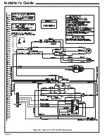
Page 18: ...Page 18 Installer s Guide Figure 20 Typical 4TCY4 Field Wiring Diagram...
Page 22: ...Page 22 Installer s Guide Notes...


