background image


                                                           Page 7

Installer’s Guide

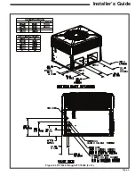
Figure 4. 4TCY4042 through 4TCY4060 (1 of 3)

NOTE: The view labeled “Bottom 
Side” represents the Base 
as viewed looking up from 
underneath the unit.

Summary of Contents for 4TCY4024

Page 1: ...be disconnected and the main gas valve must be turned off If operating checks must be performed with the unit operating it is the technician s responsibility to recognize these hazards and proceed sa...

Page 2: ...dditional respiratory protection Use the appropriate NIOSH approved respirator in these situations FIRST AID MEASURES Eye Contact Flush eyes with water to remove dust If symptoms persist seek medical...

Page 3: ...e Curb 13 Ductwork Installation 16 Attaching Downflow Ductwork to Roof Curb 16 Attaching Downflow Ductwork to Roof Frame 16 Attaching Horizontal Ductwork to Unit 16 Condensate Drain Piping 16 Air Filt...

Page 4: ...Step 2 Determine Unit Clearances Figure 1 4TCY4024 through 4TCY4036 1 of 3 Figures 1 to 6 show the unit critical dimensions NOTE The view labeled Bottom Side represents the Base as viewed looking up...

Page 5: ...Page 5 Installer s Guide Figure 2 4TCY4024 through 4TCY4036 2 of 3...

Page 6: ...Page 6 Installer s Guide Figure 3 4TCY4024 through 4TCY4036 3 of 3...

Page 7: ...Page 7 Installer s Guide Figure 4 4TCY4042 through 4TCY4060 1 of 3 NOTE The view labeled Bottom Side represents the Base as viewed looking up from underneath the unit...

Page 8: ...Page 8 Installer s Guide Figure 5 4TCY4042 through 4TCY4060 2 of 3...

Page 9: ...Page 9 Installer s Guide Figure 6 4TCY4042 through 4TCY4060 3 of 3...

Page 10: ...unit installations are illustrated in Figures 1 through 6 pages 4 9 2 Any reduction of the unit clearances indicated in these figures may result in condenser coil starvation or the recircula tion of...

Page 11: ...ast two 2 inches of insulation and weatherproof There must be a weather proof seal where the duct enters the structure 5 Do not expose the unit to direct roof water runoff 6 Seal all holes through ext...

Page 12: ...includes a kit of four 4 lifting lugs See Figure 10 inset B on page 14 2 Insert the four lifting lugs in the openings provided in the drip lip on each end of the unit See Figure 10 inset B on page 14...

Page 13: ...top applications using field fabricated ducts and sleeper rails rather than a curb or frame use the following procedure 1 Locate and secure the sleeper rails to the roof by bolting Three 3 sleeper ra...

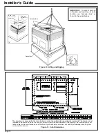
Page 14: ...drawing The manufacturer is not responsible for the unauthorized use of this drawing and expressly disclaims any liability for damages resulting from such unauthorized use Gasket Seal Spreader Bars B...

Page 15: ...rizontal Airflow Application with Frame Supply Air Return Air Roof Flashing Channel Iron Center Support Center Support required on all Frame Applica tions Angle Iron Frame Roof Flashing Return Air Ang...

Page 16: ...s to minimize noise and vibration transmission Elbows with turning vanes or splitters are recommended to minimize air noise and resistance The first elbow in the ductwork leaving the unit should be no...

Page 17: ...the only one considered Over Current Protection The branch circuit feeding the unit must be protected as shown on the unit s rating plate Power Wiring The power supply lines must be run in weather ti...

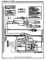
Page 18: ...Page 18 Installer s Guide Figure 20 Typical 4TCY4 Field Wiring Diagram...

Page 19: ...blower turn free without rubbing and are they tight on the shafts Has all work been done in accordance with applicable local and national codes Are all covers and access panels in place to prevent air...

Page 20: ...s are closed If two stages of heat are provided and additional heat is required the comfort control s second stage W2 circuit is energized power ing the BH contactor coil Maintenance Final Installatio...

Page 21: ...rvice routines described at the beginning of each heating season Visually inspect the unit to ensure that the airflow required for combustion and condenser coil is not obstructed from the unit Inspect...

Page 22: ...Page 22 Installer s Guide Notes...

Page 23: ...Page 23 Installer s Guide Notes...

Page 24: ...installing dealer if the unit is inoperative Before you call always check the following to be sure service is required a Be sure the main switch that supplies power to the unit is in the ON position b...

Reviews: