ASSEMBLY
Fig. 5
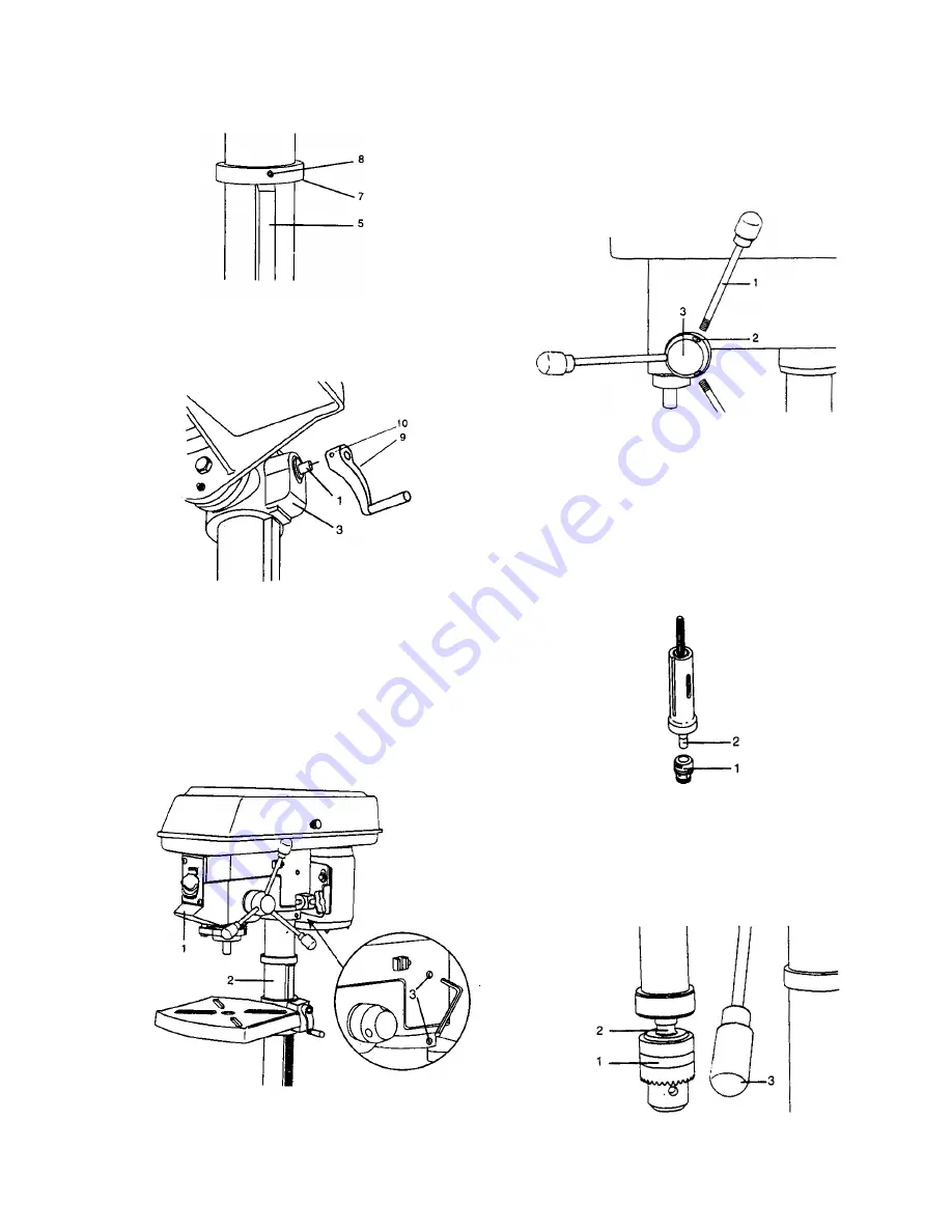
8. Install the table crank handle (9) to the worm gear shaft (1) on
the side of the table support (3 – Fig. 6).
9. Line up the flat side of the shaft with the set screw (10) in the
crank handle and tighten the screw with a hex wrench.
Fig. 6
INSTALLING THE HEAD (FIG. 7)
CAUTION!
The Drill Press head is very heavy and must be lifted with the
help of 2 PEOPLE, to safely assemble the Drill Press head on
the column.
1. Carefully lift the head (1) above the column (2) and slide it
into the column. Make sure the head slides down over the
column as far as possible. Align the head with the base.
2. Using the hex wrench, tighten the two head locking set
screws (3) on the right side of the head.
Fig. 7
INSTALLING FEED HANDLES (FIG. 8
)
1. Locate three feed handles in the loose parts bag.
2. Screw the feed handles (1) into the threaded holes (2) in
the hub (3). Tighten.
Fig. 8
INSTALLING THE CHUCK (FIG. 9, 10, 11)
1. Clean out the tapered hole in the chuck (1) with a clean
cloth.
2. Clean tapered surfaces on the spindle (2).
CAUTION:
Make sure there are no foreign particles
sticking to the surfaces or oily residue. Clean mating
parts (hole in chuck, tapered spindle) with a non-
petroleum based product such as denatured alcohol, etc.
Failure to do this can result in serious injury to the
operator. If tapered hole is extremely dirty, use a cleaning
solvent.
Fig. 9
3. Lower the spindle (2) by turning the feed handles (3)
counterclockwise.
4. Push the chuck up onto the spindle (2). Tap gently to
ensure seat.
5. Open the jaws of the chuck (1) by rotating the chuck
sleeve clockwise. To prevent damage, make sure the jaws
are completely receded into the chuck.
Fig. 10
11
Summary of Contents for DP12LW
Page 7: ...CARTON CONTENTS 7 L M N O ...
Page 22: ...22 ...


