background image


Installation

 42 


6.


Repeat the procedure for the additional processor. 

7.


Install the heat sink (on page 39). 

8.


Install the access panel (on page 24). 

Memory modules 


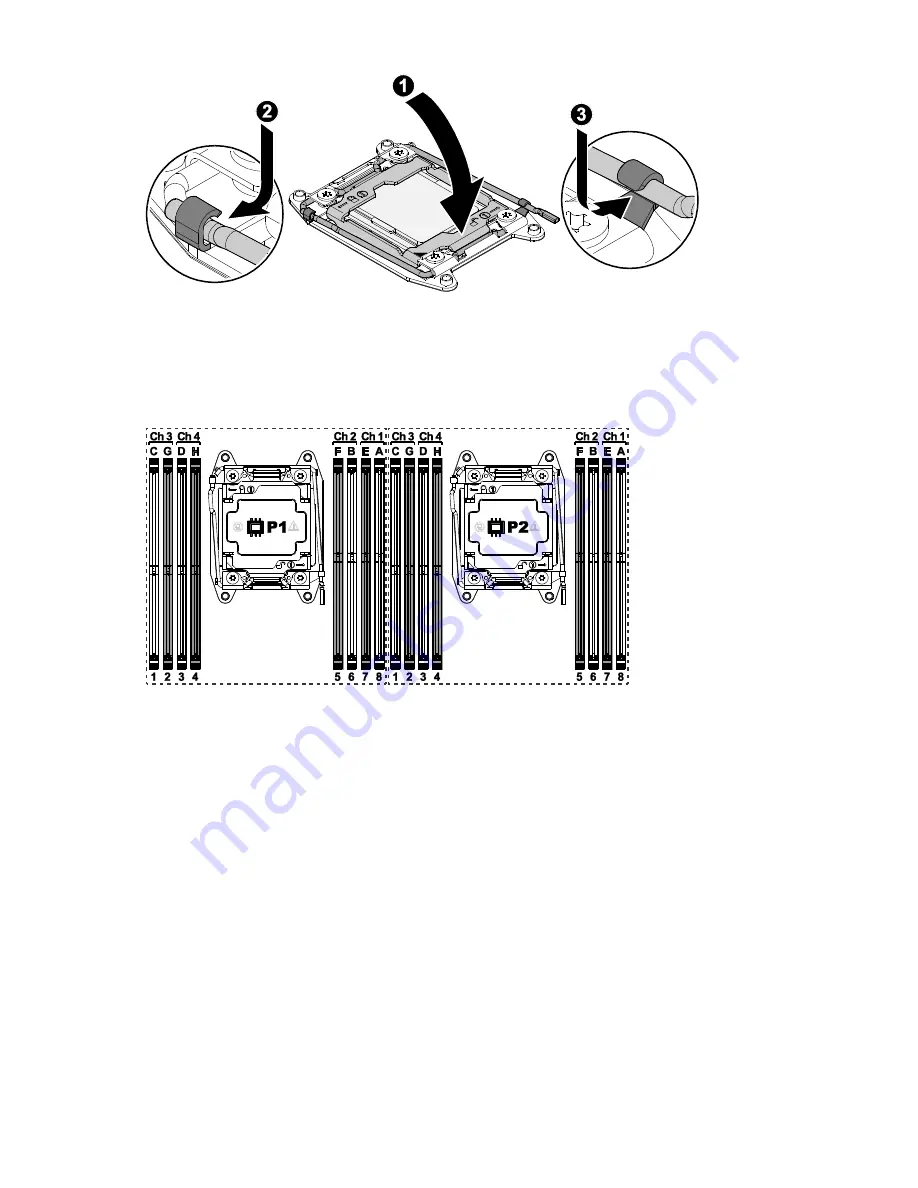
General DIMM slot population guidelines 

Observe the following guidelines for all AMP modes: 


Install DIMMs only if the corresponding processor is installed. 


When two processors are installed, balance the DIMMs across the two 
processors. 


White DIMM slots denote the first slot of a channel (Ch 1-A, Ch 2-B, Ch 3-C, 
Ch 4-D). 


Do not mix LRDIMMs, UDIMMs, RDIMMs, or HDIMMs. 


HDIMMs require 8 DIMMs per processor. 


When two processors are installed, install the DIMMs in sequential alphabetic 
order balanced between the two processors: P1-A, P2-A, P1-B, P2-B, P1-C, P2-C, 
and so on. 


Summary of Contents for R2-1218R-TH

Page 1: ...nly warranties for TradedDX products and services are set forth in the express warranty statements accompanying such products and services Nothing herein should be construed as constituting an additio...

Page 2: ...for TradeDX products and services are set forth in the express warranty statements accompanying such products and services Nothing herein should be construed as constituting an additional warranty Tra...

Page 3: ...1 Removing the 2 5 hard disk drive module 22 Redundant power supply unit 23 Removing the redundant power supply unit 23 Installing the Redundant Power Supply Unit 23 Access panel 23 Removing the acces...

Page 4: ...operating system 52 Cabling 53 Internal system cable routing 53 Configuration 55 BMC 55 Web GUI introduction 55 IP address 55 User name and password 55 Web browsers 55 Logging in 55 Updating the firm...

Page 5: ...6 Application software problems 88 ROM problems 88 Battery replacement 91 Firmware update tools 92 Firmware and drivers support 93 Firmware list 93 System board programming data 93 HDD backplane 93 HB...

Page 6: ...over 2 HDD backplane 3 Syetem fan 6 4 CPU heat sink 2 5 System board 6 OCP NIC mezzanine card SFP port x2 7 Riser assembly 2 8 SAS HBA mezzanine card 9 550W redundant PSUs 2 10 DIMM slot 16 11 Front c...

Page 7: ...LEDs and buttons Item Description 1 Power button 2 USB 2 0 2 3 UID button and LED BMC reset 4 Ethernet 1 LED 5 Ethernet 2 LED 6 IPMI LED 7 System health LED 8 Reset button LED Indicator LED Color Desc...

Page 8: ...UID Blue On Server was located for identification Off Server is operating normally System Health Green Orange Green The server is operating normally Orange Fault present on server Rear panel component...

Page 9: ...to operate high temp high power high current slow fan input voltage lower than 90Vac not warning above 90V condition must be warning state below 85V condition Storage drive LEDs LED Indicator LED Colo...

Page 10: ...n 1 NIC Link Activity LED 2 NIC Link Speed LED RJ45 Item Description 1 NIC Link Activity LED 2 NIC Link Speed LED See the following illustration to locate the system board LED indicator Item Descripti...

Page 11: ...UX Green Blink BMC is ready Off BMC is not ready LAN0 LAN1 P3V3_AUX Green Left On LAN links up but no activity Green Left Blink LAN links up with activity Left Off LAN link down Green Right On Link sp...

Page 12: ...4 Front control connector 5 HDD backplane connector 2 6 System fan header 6 7 CPU 0 8 DIMM slot 16 9 FP USB 2 0 2 10 SATA connector 2 11 MiniSAS connector 2 12 Front VGA connector 13 OCP mezzanine sl...

Page 13: ...nt of the system State Description Green on red off HDD detected Green blink red off HDD active Green off red on HDD fault Green off red blink HDD rebuilt or located Important The fault LED function i...

Page 14: ...ication 14 Item Description 1 Air baffle 2 Riser assembly 2 3 HDD backplane 4 System fan 6 5 SAS HBA mezzanine card 6 OCP NIC mezzanine card SFP port x2 7 550W redundant PSUs 2 8 System board 9 3 5 2...

Page 15: ...the IPMI command to power on system Powering down the server The following procedures show how to shut down the server and verify the power status Shutting down the server Graceful shutdown To perform...

Page 16: ...Operations 16 Verifying the power status Verify all power LED indicators of the server and make sure the power LED light is off before replacing and removing the server components from the rack...

Page 17: ...touching the bare metal chassis of the computer case or the bare metal body of any other grounded appliance Hold electronic circuit boards only by the edges Do not touch the components on the board u...

Page 18: ...Installation 18 Hard disk drives Removing the hot swappable HDD assembly Installing the hot swappable hard disk drive assembly Verify that the drive is fully seated...

Page 19: ...HDD assembly on page 18 2 Remove the screws securing the filler panel from the HDD carrier 3 Remove the filler panel from the HDD carrier 4 Align the HDD in the HDD carrier with the connectors facing...

Page 20: ...ng the 3 5 hard disk drive module To remove the 3 5 hard disk drive module 1 Remove the hot swappable HDD assembly on page 18 2 Remove the screws securing the HDD from the HDD carrier 3 Remove the HDD...

Page 21: ...er panel from the HDD carrier 3 Remove the filler panel from the HDD carrier 4 Align the holes on the HDD bracket with the holes on the HDD carrier 5 Secure the HDD bracket and the HDD carrier with sc...

Page 22: ...ge 18 Removing the 2 5 hard disk drive module To remove the 2 5 hard disk drive module 1 Remove the hot swappable HDD assembly on page 18 2 Turn the HDD assembly over 3 Remove the screws securing the...

Page 23: ...Removing the redundant power supply unit Installing the Redundant Power Supply Unit Access panel Removing the access panel CAUTION Be sure that the server is powered down and the AC power cords are d...

Page 24: ...ing the access panel Air baffle Removing the air baffle To remove the air baffle 1 Power off the server and detach all of the power cords from the power supplies 2 Remove the access panel on page 23 3...

Page 25: ...talling the air baffle To install the air baffle 1 Position the air baffle in the chassis see the following figure CAUTION To avoid damaging the server components do not use force when removing the ai...

Page 26: ...the power supplies 2 Remove the access panel on page 23 3 Remove the hot swappable HDD assembly on page 18 4 Disconnect the cables from the HDD backplane assembly 5 Release the HDD backplane assembly...

Page 27: ...n the assembly bracket 1 2 Install the HDD backplane to the assembly bracket 3 Install and secure the HDD backplane with the screws 2 4 Align the HDD backplane assembly to the guide tabs on the chassi...

Page 28: ...3 Lift the fan module from the chassis Installing the system fan assembly To install the system fan assembly CAUTION Avoid damaging the fan cable 1 Align the guide pins on the fan assembly with the g...

Page 29: ...fan cage To remove a system fan assembly 1 Power off the server and detach all of the power cords from the power supplies 2 Remove the access panel on page 23 3 Remove the system fan assembly on page...

Page 30: ...ng the system fan cage To install the system fan assembly 1 Align the fan cage with the system board 2 Flip the handle to secure the fan cage 3 Install the system fan assembly on page 28 4 Install the...

Page 31: ...stem fan cage support bracket 1 Power off the server and detach all of the power cords from the power supplies 2 Remove the access panel on page 23 3 Remove the system fan assembly on page 28 4 Remove...

Page 32: ...support bracket 1 Make sure the front VGA MiniSAS and front control cables are tucked under the support bracket 2 Secure the support bracket and the chassis with screws 3 Install the system fan cage...

Page 33: ...ews securing the front control panel cover to the chassis See the following figure to locate the screws and then use a screwdriver to loosen and remove them 1 3 Hold the front control panel and then g...

Page 34: ...front control board 1 Connect the front control board with the front control board cable 3 2 Secure the front control board to the chassis with the screw 2 3 Install the front control panel cover 4 S...

Page 35: ...on page 23 3 Remove the system fan assembly on page 28 4 Remove the system fan cage on page 29 5 Remove the system fan cage support bracket on page 31 6 There are three screws securing the front VGA c...

Page 36: ...e the screw that is securing the front VGA cable 1 11 Grasp the front VGA cable and gently pull it through the front of the chassis Installing the front VGA cable To install the front control board 1...

Page 37: ...Installation 37 3 Put the front VGA cable in the HDD partition L 4 Secure the HDD partition L and the chassis with screws...

Page 38: ...sors To achieve optimal cooling performance the underside of the heat sink must be properly attached to the processor with TIM The mechanical performance of the heat sink is designed to meet the requi...

Page 39: ...e of the heat sink 3 Place the heat sink on top of the CPU until it is seated firmly in place 4 Tighten the four retaining screws clockwise in the order shown to secure the heat sink 5 Repeat for the...

Page 40: ...4 Press downward and outward on the right processor locking lever to release it 5 Press downward and outward on the left processor locking lever pulling it fully open 6 Press downward on the right pr...

Page 41: ...gular cutout of the socket and the key indent on the socket 2 Insert the processor into the socket being sure that the four keys on the socket fit into the corresponding keys on the processor 3 Lower...

Page 42: ...l DIMMs only if the corresponding processor is installed When two processors are installed balance the DIMMs across the two processors White DIMM slots denote the first slot of a channel Ch 1 A Ch 2 B...

Page 43: ...ower off the server and then detach all of the power cords from the power supplies 2 Remove the access panel on page 23 3 Push the locking latches of the DIMM slot downward and outward to eject the me...

Page 44: ...wer cords from the power supplies 2 Remove the access panel on page 23 3 Remove the system fan assembly on page 28 4 Remove the system fan cage on page 29 5 Remove the riser assembly on page 46 6 Remo...

Page 45: ...sis 2 Install the system board into the chassis 3 Secure the system board to the chassis with the screws 4 Connect the cables 5 Install the processors on page 41 6 Install the heat sinks on page 39 7...

Page 46: ...Power down the server and then detach all of the power cords from the power supplies 2 Remove the access panel on page 23 3 Grasp the riser assembly and then gently lift the riser assembly up to remov...

Page 47: ...the riser holder bracket with the screw hole on the riser body bracket 2 Secure the riser holder bracket to the riser body bracket with thumb screw 3 Turn the riser assembly over to align with the PC...

Page 48: ...wer cords from the power supplies 2 Remove the access panel on page 23 3 Remove the riser assembly on page 46 4 Remove the screws securing the riser board and the riser body bracket 5 Remove the riser...

Page 49: ...the OCP mezzanine card To remove the OCP mezzanine card 1 Power off the server and then detach all of the power cords from the power supplies 2 Remove the access panel on page 23 3 Remove the riser as...

Page 50: ...he OCP mezzanine card 1 Align the connector on the OCP mezzanine card with the slot on the system board 2 Gently install the OCP mezzanine card 3 Secure the OCP mezzanine card to the chassis with scre...

Page 51: ...A mezzanine card 1 Power down the server and then detach all of the power cords from the power supplies 2 Remove the access panel on page 23 3 Remove the riser assembly on page 46 4 Remove the screws...

Page 52: ...fault settings press F2 or DEL when prompted from the start up sequence to enter the BIOS setup utility By default the BIOS setup utility runs in the English language o It is not necessary to modify t...

Page 53: ...g 1 without HBA mezzanine card Item Description Quantity 1 Front VGA cable 1 from system board 2 Front control USB cable 1 from system board 3 HDD backplane power cable 1 from HDD backplane 4 1 MiniSA...

Page 54: ...t control USB cable 1 from system board 3 HDD backplane power cable 1 from HDD backplane 4 1 MiniSAS cable 1 HDD backplane to HBA mezzanine card 1 from HDD backplane 4 2 MiniSAS cable 2 HDD backplane...

Page 55: ...nd DHCP are the two common IP sources of iBMC FW The default setting is DHCP The detailed IP address information is available from the BIOS setup menu User name and password A user name and password a...

Page 56: ...minor revision BCD encoded and y is auxiliary firmware revision y is a if auxiliary firmware revision is 0 and y is b if auxiliary firmware revision is 1 and so on For example if the firmware revisio...

Page 57: ...O network stack CSM USB serial port console redirection PCI subsystem settings and trusted computing IntelRCSetup Configuration information for the processor advanced power management common RefCode Q...

Page 58: ...Number E R Type Event Data1 Event Data2 Event Data3 Description BIOS POST Sensor 0x0F 0x09 0x6F 0xC0 0x01 0xFF System firmware error No system memory is physically installed in the system 0x0F 0x6F 0...

Page 59: ...4 Use the up and down arrow keys to scroll up and down to select an item on a top level screen When the up and down arrow keys are pressed the only options that are highlighted are the options that c...

Page 60: ...done o X Do not check ROM ID o S Display current system s BIOS ROM ID o R Preserve all SMBIOS structures during NVRAM programming o Rn Preserve SMBIOS type N during Boot Block programming o ECUF Updat...

Page 61: ...rd that was set by the user is still reserved Recovering the BIOS If the BIOS image is corrupt a system BIOS update fails or the system fails to complete POST the BIOS must enter recovery mode In reco...

Page 62: ...COVERY MODE 1 2 Default Normal operation 2 3 Force BIOS to enter recovery mode J16 PASSWORD CLEAR 1 2 Default Normal operation 2 3 Password clear J19 ME FIRMWARE UPDATE 1 2 Normal operation 2 3 ME fir...

Page 63: ...on using Linux 1 Log into Linux 2 Open the terminal Execute the dmidecode t 0 command to display the BIOS version as shown in the following figure Checking the BIOS version using the BIOS setup utilit...

Page 64: ...the terminal Execute the ipmitool I open mc info command to display the BMC version as shown in the following figure Checking the event log Checking the system event log using Linux remote desktop 1...

Page 65: ...t command to check the system event log The system event log is shown in the following figure Checking the event log using the BIOS setup utility System Event Logs To check the event log using the BIO...

Page 66: ...Configuration 66 2 Use the arrow keys to select System Event Log and then press Enter The System Event Log displays SMBIOS 1 Enter the BIOS setup and then select the Event Logs menu...

Page 67: ...Configuration 67 2 Use the arrow keys to select View SMBIOS Event Log and then press Enter The SMBIOS Event Log displays...

Page 68: ...Diagrams 68 Diagrams System board diagram...

Page 69: ...ower on Does the server complete POST If not then what do the health LEDs indicate Is video display available If the server completes POST and video is available are there any POST error messages Reco...

Page 70: ...e all external peripherals such as the network cables monitor keyboard and mouse 4 Collect all tools and utilities necessary to troubleshoot the problem such as a Torx screwdriver loopback adapters ES...

Page 71: ...and maintenance guide Always use the recommended minimum configuration above before removing any processors If you are unable to isolate the issue with the configuration above you will then remove al...

Page 72: ...hart on page 74 The General diagnosis flowchart is a generic troubleshooting process to be used when the problem is not server specific or is not easily categorized into the other flowcharts The avail...

Page 73: ...sis Does the server complete POST Does the server boot to the OS Go to Remote Diagnosis Go to general Diagnosis Go to Power on problems Go to POST problems Go to OS Boot Problems Yes Yes NO NO NO Yes...

Page 74: ...dministrator to Troubleshoot the server Does the condition still exist End Download OS system log and BMC log Contact Support RDS BMC No Yes No Yes General diagnosis flowchart The General diagnosis fl...

Page 75: ...guration Does the Condition still Exist Isolate and minimize the Memory configuration Troubleshoot or replace basic server spare parts Does the Condition still exist Break server down To minimal confi...

Page 76: ...LED flashing green or solid green Press the power On Standby button And wait 45seconds Is the power Source operating properly Replace the power source Does condition still exIst End Replace the power...

Page 77: ...t the Indicated Component Check for loose connections If condition still exists replace indicated component Does the error code Provide direction Check the error symptom in Troubleshooting specificati...

Page 78: ...iver compatibility issues The virus Reinstall the operation system Reboot and Enter The safe Mode Successfully Does the crash blue screen Auto reboot And some error info symptom exist Start OS boot pr...

Page 79: ...tware Update the software or re install the system 3 System stopped issue Track the reasons the system stopped from the software and hardware respectively o Software tracking Check the system event lo...

Page 80: ...nce for the system When handling a DIMM observe the following guidelines Avoid electrostatic discharge Always hold DIMMs by the side edges only Avoid touching the connectors on the bottom of the DIMM...

Page 81: ...ure no loose connections exist 2 If the power supplies have LEDs be sure they indicate that each power supply is working properly If the LEDs indicate a problem with a power supply 6 7Hz flashes green...

Page 82: ...nsider using a different memory module to verify it is a memory problem Third party device problems 1 See the device documentation to be sure the device is properly installed 2 If the device is the on...

Page 83: ...repair utility for the operating system o Be sure no viruses exist on the server Run a current version of a virus scan utility o Be sure the TPM is enabled in BIOS o Be sure the firewall setting is co...

Page 84: ...ze Action Install a memory module of a supported size o Incomplete bank detected in bank X Possible cause The bank is missing one or more DIMMs Action Fully populate the memory bank o Mismatched DIMMs...

Page 85: ...anced ECC with hot add support Possible cause Advanced ECC with hot add support is enabled Action None Processor problems Be sure that the server supports each processor and that each processor is cor...

Page 86: ...e no loose connections exist Be sure the keyboard or and mouse is connected to the correct ports Be sure the keyboard or mouse is clean Be sure legacy support for USB is enabled in the BIOS Replace th...

Page 87: ...iously saved version of the system Before restoring the backup make a backup of the current system If restoring the previous system does not correct the problem you can restore the current set to be s...

Page 88: ...original configuration Errors occur after the system software is changed Change settings to the original configuration If more than one setting is changed change the settings one at a time to isolate...

Page 89: ...and correct the cause of connection failure and then restart the process 5 Failure occurs during ROM flash The flash cannot be interrupted during this process or the ROM image is corrupted and the se...

Page 90: ...Diagnostic flowcharts 90 7 Power up the server 8 If both the current and backup versions of the ROM are corrupt return the system board for a service replacement...

Page 91: ...n 60 C 140 F Do not disassemble crush puncture short external contacts or dispose of in fire or water Replace only with the spare designated for this product To remove the component 1 Power down the s...

Page 92: ...are the system firmware types support OS utility for firmware update and supported server mode Firmware Type Supported OS Server Mode Firmware Tool System BIOS DOS Offline AFUDOS exe BMC DOS Offline B...

Page 93: ...BMC CPLD LAN EEPROM I350 HDD backplane CPLD FW HBA RAID card LSI2308 HBA Card FW optional 10G OCP mezzanine card 82599 10G OCP Flash 82599 10G OCP EEPROM Fan speed control Fan Speed control Device dri...

Page 94: ...residential area is likely to cause harmful interference in which case the user will be required to correct the interference at his own expense European Union regulatory notice Products bearing the C...

Page 95: ...tive foreign objects could produce a short circuit that could cause fire electric shock or damage to your equipment Safety Instructions 1 Please read these safety instructions carefully 2 Please keep...

Page 96: ...ing symbols may be placed on the equipment to indicate the presence of potential hazardous condition This symbol indicates the presence of hazardous energy circuits or electric shock hazards Refer all...

Page 97: ...edures other than those specified herein might result in hazardous radiation exposure Some laser products contain an embedded Class 3A or Class 3B laser diode Note the following Laser radiation when o...

Page 98: ...lling moving or opening covers on this product or attached devices To Connect To Disconnect 1 Turn everything OFF 2 First attach all cables to devices 3 Attach signal cables to connectors 4 Attach pow...

Page 99: ...ord into a grounded earthed electrical outlet that is easily accessible at all times Unplug the power cord from the power supply to disconnect power to the equipment Do not route the power cord where...

Page 100: ...gainst the skin to provide proper ground Use heel straps toe straps or boot straps at standing workstations Wear the straps on both feet when standing on conductive floors or dissipating floor mats Us...

Page 101: ...vel An altitude derating of 1 C per 304 8 m 1 8 F per 1 000 ft to 3048 m 10 000 ft is applicable No direct sunlight allowed Mechanical specifications Specification Value Height 87 mm 3 43 in Depth 711...

Page 102: ...contacts Before you contact TradeDX Be sure to have the following information available before you call TradeDX Technical support registration number if applicable Product serial number Product model...

Reviews: