Electrical Control Function
110
Electrical Control System
Bit0
Frequency limit
caused by voltage
16
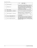
DC fan motor speed
17
IGBT radiator temp.
The display value is between 30~120 degree. If the temp. is
lower than 30 degree, the digital display tube will show “30”.If
the temp. is higher than 99 degree, the digital display tube will
show single digit and tens digit. (For example, the digital
display tube show “0.5”,it means the IGBT radiator temp. is
105 degree. the digital display tube show “1.6”,it means the
IGBT radiator temp. is 116 degree)
18
Indoor unit number
The indoor unit can communicate with outdoor unit well.
19
Condenser pipe temp. of 1# indoor unit
If the temp. is lower than 0 degree, the digital display tube will
show “0”.If the temp. is higher than 70 degree, the digital
display tube will show “70”. If the capacity demand is 0, , the
digital display tube will show “0. If the indoor unit is not
connected, the digital display tube will show: “
――
”(heating
T2
,
cooling T2B)
20
Condenser pipe temp. of 2# indoor unit
21
Condenser pipe temp. of 3# indoor unit
22
1# Indoor unit capacity demand code
Actual data*HP*10
If capacity demand code is higher than 99, the digital display
tube will show single digit and tens digit. (For example, the
digital display tube show “5.0”,it means the capacity demand
is 15. the digital display tube show “60”,it means the capacity
demand is 6.0). If the indoor unit is not connected, the digital
display tube will show: “
――
”
23
2# Indoor unit capacity demand code
24
3# Indoor unit capacity demand code
Summary of Contents for CCT 140IUINV
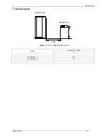
Page 13: ...Service Space Super Slim Cassette Type 13 3 Service Space 1000mm 1000mm 1000mm 1000m m ...
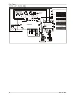
Page 14: ...Wiring Diagrams 14 Super Slim Cassette Type 4 Wiring Diagram CCT140 IUINV CCT160 IUINV ...
Page 26: ...Wiring Diagrams Duct Type 27 4 Wiring Diagrams DCT140 IUINV DCT160 IUINV ...
Page 32: ...Field Wiring Duct Type 33 10 Field Wiring ...
Page 35: ...Service Space Ceiling Floor Type 37 3 Service Space ...
Page 36: ...Wiring Diagrams 38 Ceiling Floor Type 4 Wiring Diagrams CFT140 IUINV CFT160 IUINV ...
Page 41: ...Field Wiring Ceiling Floor Type 43 9 Field Wiring ...
Page 45: ...Service Space GA Floor standing Type 47 3 Service Space ...
Page 46: ...Wiring Diagrams 48 GA Floor standing Type 4 Wiring Diagrams FS140IUINV FS160IUINV ...
Page 56: ...Wiring Diagrams 70 Outdoor Units OU 1403 IUINV OU 1603 IUINV ...
Page 80: ...Troubleshooting Electrical Control System 121 2 4 2 3 Up down panel is not closed ...
Page 88: ...Troubleshooting Electrical Control System 129 2 4 3 8 P0 malfunction ...
Page 89: ...Troubleshooting 130 Electrical Control System 2 4 3 9 P1 malfunction ...
Page 90: ...Troubleshooting Electrical Control System 131 2 4 3 10 P2 malfunction ...
Page 91: ...Troubleshooting 132 Electrical Control System 2 4 3 11 P3 malfunction ...


