background image

Troubleshooting 


112 

Electrical Control System


2.1.5 Display board of GA floor standing 


2.1.6 Display board of M floor- standing 


Summary of Contents for CCT 140IUINV

Page 1: ... MODEL CCT 140IUINV OU1403 INV CCT 160IUINV OU1603 INV DCT 140IUINV OU1403 INV DCT 160IUINV OU1603 INV CFT 140IUINV OU1403 INV CFT 160IUINV OU1603 INV FS 140IUINV OU1403 INV FS 160IUINV OU1603 INV Refrigerant R 410A ...

Page 2: ...i Part 1 General Information Part 2 Indoor Units Part 3 Outdoor Units Part 4 Electrical Control System The specifications designs and information in this book are subject to change without notice for product improvement ...

Page 3: ...General Information General Information 1 Part 1 General Information 1 Model Lists 2 2 Features 4 ...

Page 4: ...1 1 Indoor Units R410A Capacity multiplied by 1000Btu h Type Function 48 60 Super slim four way cassette Cooling and heating x x 3 rd generation ceiling floor Cooling and heating x x Duct Cooling and heating x x floor standing Cooling and heating x x ...

Page 5: ...ient kit is standard for outdoor units 2 4 Network control function is standard for the indoor units 2 5 Standard auto restart function and follow me function 2 6 Cassette ceiling floor with standard remote controller wire controller and CCM for optional Med Duct with standard wired controller remote controller and CCM for optional 2 7 Standard anti cold air function 2 8 Standard auto defrosting f...

Page 6: ...Indoor Units 6 Super Slim Cassette Type Part 2 Indoor Units Super Slim Cassette Type Duct Type Ceiling Floor Type GA Floor standing Type ...

Page 7: ...Super Slim Cassette Type 1 Features 8 2 Dimensions 12 3 Service Space 13 4 Wiring Diagrams 14 5 Air Velocity and Temperature Distributions Reference Data 15 6 Electric Characteristics 16 7 Sound Levels 17 8 Accessories 18 9 The Specification of Power 19 ...

Page 8: ...ign more convenient to clean and maintain the filter optional Old Cassette New slim cassette Volume change Dimension 18K 24K 840 230 840 18K 24K 840 205 840 11 30K 840 300 840 30K 840 205 840 32 36K 48K 840 300 840 36K 48K 840 245 840 18 48K 60K 840 300 840 48K 60K 840 287 840 4 1 2 Fresh air intake function Fresh air fulfills air quality more healthy and comfortable Ventilation motor is optional ...

Page 9: ... be switched on or off by remote controller When pressing the Clean Air button on the remote controller Ionizer will work and the indicator light on display board will shine New air intake I Io on ni iz ze er r g ge en ne er ra at to or r c co on nn ne ec ct to or r V Ve en nt ti il la at ti io on n m mo ot to or r c co on nn ne ec ct to or r ...

Page 10: ...gn Reserve external air duct more flexible for the air supply 1 5 Built in draining pump Due to the improvement of structure more convenient to repair or replace the draining pump Built in draining pump to make sure condensed water drain out reliably Draining Pump ...

Page 11: ... distance on off controller more human control 1 7 Optional touch screen wired controller Touch screen wired controller is optional with error code indication function Better man machine conversation interface Undated structure design 4 way wire layout design no raised part at backside more convenient to place the wires and install the device Alarm lamp Long distance on off controller ...

Page 12: ...Dimensions 12 Super Slim Cassette Type 2 Dimensions Model A H CCT140IUINV 287 317 CCT160IUINV 287 317 ...

Page 13: ...Service Space Super Slim Cassette Type 13 3 Service Space 1000mm 1000mm 1000mm 1000m m ...

Page 14: ...Wiring Diagrams 14 Super Slim Cassette Type 4 Wiring Diagram CCT140 IUINV CCT160 IUINV ...

Page 15: ...elocity Electronic expansionvalve Oil separator Compressor Lowpressure switch Oil return Capillary Highpressureswitch Lowpressureliquid accumulator Evaporator Capillary Outdoor unit Indoorunit 4 wayvalve Condenser T5 Dischargetemp sensor Filter Filter Condensertemp sensor T3 T4 Ambienttemp sensor Filter Filter T2 Evaporatortemp sensor Roomtemp sensor T1 ...

Page 16: ...acteristics 16 Super Slim Cassette Type 6 Electric Characteristics Model Indoor Unit Power Supply Hz Voltage Min Max MFA CCCT140IUINV 50 220 240 198 254 10 CCT160IUINV 50 220 240 198 254 10 Notes MFA Max Fuse Amps A ...

Page 17: ...Sound Levels Super Slim Cassette Type 17 7 Sound Levels 1 4m Microphone Model Noise level dB A H M L CCT140IUINV 53 50 46 CCT160IUINV 54 51 46 ...

Page 18: ...Out let pipe sheath 1 Out let pipe clasp 1 Remote controller Its Frame Remote controller Its Frame 1 Remote controller holder 1 Mounting screw ST2 9 10 C H 2 Remote controller manual 1 Alkaline dry batteries AM4 2 Others Owner s manual 1 Installation manual 1 Network wires 1 Installation accessory The product you have might not be provided the following accessories Expansible hook 4 Installation h...

Page 19: ...ase Frequency and Voltage 220 240V 50Hz Power Wiring mm2 3 1 0 Circuit Breaker Fuse A 15 10 OUTDOOR UNIT POWER Phase 3 phase Frequency and Voltage 380 415V 50Hz Power Wiring mm2 3 4 0 Circuit Breaker Fuse A 40 35 Indoor Outdoor Connecting Wiring Weak Electric Signal mm 2 3 1 5 Indoor Outdoor Connecting Wiring Strong Electric Signal mm2 ...

Page 20: ... 21 Duct Type 1 Features 22 2 Dimensions 25 3 Service Space 26 4 Wiring Diagrams 27 5 Static Pressure 28 6 Electric Characteristics 29 7 Sound Levels 30 8 Accessories 31 9 The Specification of Power 32 10 Field Wiring 33 ...

Page 21: ...rear to the bottom in order to matching the installation condition 1 3 Fresh air intake function Optional for 18 60k Install one duct from the reserved fresh air intake to outdoor Continually inhale the fresh air to improve the quality of the indoor air fulfills air quality more healthy and comfortable 1 4 Easy maintenance Clean the filter Optional standard product without filter It is easy to dra...

Page 22: ...ote on off and central control ports Reserved remote on off ports and central control ports can connect the cable of an on off controller or a central controller to realize remote on off control function or group control function 1 6 Built in drain pump Optional Built in drain pump can lift the water to 750mm upmost It s convenient to install drainage piping under most space condition Motor Blower...

Page 23: ...ith a receiver in the E box Move out the display and fix it in other place even in the distance of 10m The unit will realized remoter control The wired controller and the display board can display the error code or production code when the chips detect some failure Display 750mm upmost Wired Controller Standard Remote Controller Optional ...

Page 24: ... Outline dimension mm Air outlet opening size Air return opening size Size of outline dimension mounted plug A B C D E F G H I J K L M DCT 140 IUINV 1200 300 865 800 80 968 40 204 1094 288 45 1240 500 DCT160IUINV 1200 300 865 800 80 968 40_204 1094 288 45 1240 500 ...

Page 25: ...Service Space 26 Duct Type 3 Service Space Ensure enough space required for installation and maintenance All the indoor units reserve the hole to joint the fresh air pipe The hole size as following ...

Page 26: ...Wiring Diagrams Duct Type 27 4 Wiring Diagrams DCT140 IUINV DCT160 IUINV ...

Page 27: ... 1300 Mid speed High speed External static pressure Pa 3 Air volume m h 1000 90 80 70 60 50 40 30 20 10 Low speed 1600 1900 2800 3100 120 110 Super high speed 3400 100 3100 2800 1900 1600 Low speed 10 20 30 40 50 60 70 80 90 Pa 1000 Air volume m h 3 External static pressure Pa High speed Mid speed 1300 2200 2500 ...

Page 28: ...ric Characteristics Duct Type 29 6 Electric Characteristics Model Indoor Unit Power Supply Hz Voltage Min Max MFA DCT140IUINV 50 220 240 198 254 10 DCT160IUINV 50 220 240 198 254 10 Notes MFA Max Fuse Amps A ...

Page 29: ...Sound Levels 30 Duct Type 7 Sound Levels Suction Discharge Microphone 1 4m Concealed Duct Type Duct Duct Model Noise level dB A H M L DCT140IUINV 45 41 37 DCT160IUINV 45 41 37 ...

Page 30: ...ation sheath 2 Binding tape 1 Seal sponge 1 Drainpipe Fittings for cooling heating Drain joint 1 Seal ring 1 Wired controller Its Frame Wired controller 1 Others Owner s manual 1 Installation manual 1 EMS It s fitting Magnetic ring twist the electric wires L and N around it to five circles 1 ...

Page 31: ...oltage 220 240V 50Hz 220 240V 50Hz 220 240V 50Hz Power Wiring mm2 3 1 0 3 1 0 3 1 0 Circuit Breaker Fuse A 15 10 15 10 15 10 OUTDOOR UNIT POWER Phase 3 phase Frequency and Voltage 380 415V 50Hz Power Wiring mm2 5 2 5 Circuit Breaker Fuse A 30 25 Indoor Outdoor Connecting Wiring Weak Electric Signal mm 2 3 0 5 Indoor Outdoor Connecting Wiring Strong Electric Signal mm2 ...

Page 32: ...Field Wiring Duct Type 33 10 Field Wiring ...

Page 33: ... Ceiling Floor Type Ceiling Floor Type 1 Features 35 2 Dimensions 36 3 Service Space 37 4 Wiring Diagrams 38 5 Electric Characteristics 39 6 Sound Levels 40 7 Accessories 41 8 The Specification of Power 42 9 Field Wiring 43 ...

Page 34: ...ng 1 3 Two direction auto swing vertical horizontal and wide angle air flow Air flow directional control minimizes the air resistance and produces wilder air flow to vertical direction The range of horizontal air discharge is widened which secures wider air flow distribution to provide more comfortable air circulation no matter where the unit is set up 1 4 Three level fan speed more humanism desig...

Page 35: ...Service Space Ceiling Floor Type 37 3 Service Space ...

Page 36: ...Wiring Diagrams 38 Ceiling Floor Type 4 Wiring Diagrams CFT140 IUINV CFT160 IUINV ...

Page 37: ...acteristics Ceiling Floor Type 39 5 Electric Characteristics Model Indoor Units Power Supply Hz Voltage Min Max MFA CFT140IUINV 50 220 240V 198V 242V 10 CFT160IUINV 50 220 240V 198V 242V 10 Note MFA Max Fuse Amps A ...

Page 38: ...Sound Levels 40 Ceiling Floor Type 6 Sound Levels Microphone 1m 1m Air outlet side 1 5m 1m Microphone Ceiling Floor Model Noise level dB A H M L CFT140IUINV 57 54 52 CFT160IUINV 56 53 51 ...

Page 39: ...7 Accessories Remote controller Its holder 1 Remote controller 1 2 Remote controller holder 1 3 Mounting screw ST2 9 10 C H 2 4 Alkaline dry batteries AM4 2 Others 5 Owner s manual 1 6 Installation manual 1 7 Remote controller manual 1 ...

Page 40: ...nd Voltage 220 240V 50Hz 220 240V 50Hz 220 240V 50Hz Power Wiring mm 2 3 1 0 3 1 0 3 1 0 Circuit Breaker Fuse A 15 10 15 10 15 10 OUTDOOR UNIT POWER Phase 3 phase Frequency and Voltage 380 415V 50Hz Power Wiring mm 2 5 2 5 Circuit Breaker Fuse A 50 40 Indoor Outdoor Connecting Wiring Weak Electric Signal mm2 3 0 5 Indoor Outdoor Connecting Wiring Strong Electric Signal mm2 ...

Page 41: ...Field Wiring Ceiling Floor Type 43 9 Field Wiring ...

Page 42: ... 错误 未定义书签 2 Dimensions 错误 未定义书签 3 Service Space 错误 未定义书签 4 Wiring Diagrams 错误 未定义书签 5 Air Velocity and Temperature distributions Reference Data 错误 未定义书 签 6 Electric Characteristics 错误 未定义书签 7 Sound Levels 错误 未定义书签 8 Accessories 错误 未定义书签 9 The Specification of Power 错误 未定义书签 错误 未定义书签 ...

Page 43: ...off the air outlet louver of the unit can be closed manually to prevent the dust falling in 1 3 Simple and bright panel Adopts simple and bright style panel GA series are suitable for most different space and show in good taste 1 4 Big LCD display easy to read and to operate 1 5 Optional GA1 GA2 panel healthy filter and auto restart function ...

Page 44: ...Dimensions 46 GA Floor standing Type 2 Dimensions Dimension Mode W mm D mm H mm FS140IUINV 610 390 1925 FS160IUINV 610 390 1925 ...

Page 45: ...Service Space GA Floor standing Type 47 3 Service Space ...

Page 46: ...Wiring Diagrams 48 GA Floor standing Type 4 Wiring Diagrams FS140IUINV FS160IUINV ...

Page 47: ...Air Velocity and Temperature Distrib GA Floor standing Type 49 5 Air Velocity and Temperature Distributions Reference Data Model 48K 60K Airflow velocity Temperature ...

Page 48: ...tics 50 GA Floor standing Type 6 Electric Characteristics Model Indoor Units Power Supply Hz Voltage Min Max MFA FS140IUINV______ 50 380 420V 342V 440V 16 FS160IUINV______ 50 380 420V 342V 440V 16 Note MFA Max Fuse Amps A ...

Page 49: ...Sound Levels GA Floor standing Type 51 7 Sound Levels Model Noise level dB A H M L FS140IUINV______ 58 54 49 FS160IUINV______ 58 54 49 ...

Page 50: ... Self tapping Screw 3 9 25 2 3 Flat Washers 2 4 Bushing Sleeve Cover 1 5 Sound Heat Insulation Sleeves 2 6 Seal 1 7 Drain joint 1 8 Pipe hole protection Ring 1 9 Remote Battery 2 10 Remote Controller 1 11 Connection Cables 1 12 Remote controller manual 1 13 User s manual 1 14 Installation manual 1 ...

Page 51: ...R UNIT POWER Phase Frequency and Voltage POWER WIRING mm 2 CIRCUIT BREAKER A OUTDOOR UNIT POWER Phase 3 phase Frequency and Voltage 380 420V 50Hz POWER WIRING mm 2 5 2 5 CIRCUIT BREAKER A 30 Indoor Outdoor Connecting Wiring Weak Electric Signal mm 2 3 0 5 Indoor Outdoor Connecting Wiring Strong Electric Signal mm 2 ...

Page 52: ...Outdoor Units Outdoor Units 65 Part 3 Outdoor Units 1 Dimensions 66 2 Service Space 67 3 Piping Diagrams 68 4 Wiring Diagrams 69 5 Electric Characteristics 71 6 Operation Limits 72 7 Sound Levels 73 ...

Page 53: ...Dimensions 66 Outdoor Units 1 Dimensions Model Unit mm A B C D E F H OU 1403INV 938 633 5 404 448 370 392 1369 OU 1603INV ...

Page 54: ...Service Space Outdoor Units 67 2 Service Space More than 60cm More than 30cm More than 60cm More than 200cm Air inlet Air inlet More than 30cm Air outlet Wall or obstacle Maintain channel ...

Page 55: ...or 2 WAY VALVE 3 WAY VALVE 4 WAY VALVE COOLING HEATING T2B Evaporator temp sensor outlet T1 Room temp sensor T3 Condenser temp sensor Accumulator T5 Discharge temp sensor High pressure switch T4 Ambient temp sensor Low pressure switch INDOOR OUTDOOR Oil return Capillary Oil separator T2 Evaporator temp sensor middle Electronic expansion valve CAPILIARY TUBE ...

Page 56: ...Wiring Diagrams 70 Outdoor Units OU 1403 IUINV OU 1603 IUINV ...

Page 57: ...Electric Characteristics Outdoor Units 71 5 Electric Characteristics Model Outdoor Unit Hz Voltage Min Max OU 1403INV____ 50 380 415 342 440 OU 1603INV____ 50 380 415 342 440 ...

Page 58: ... above conditions certain safety protection features may come into operation and cause the unit to operate abnormally 2 The room relative humidity should be less than 80 If the air conditioner operates beyond this figure the surface of the air conditioner may attract condensation Please set the vertical air flow louver to its maximum angle vertically to the floor and set HIGH fan mode 3 The optimu...

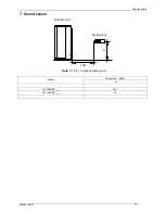
Page 59: ...Sound Levels Outdoor Units 73 7 Sound Levels H 1 0m Outdoor Unit Microphone Note H 0 5 height of outdoor unit Model Noise level dB A H OU 1403INV____ 62 5 OU 1603INV____ 62 ...

Page 60: ...Electrical Control System Electrical Control System 101 Part 4 Electrical Control System 1 Electrical Control Function 2 Troubleshooting 3 Controller ...

Page 61: ...r fan delayed open function For floor standing When the unit starts up the louver will be active immediately and the indoor fan will open 5s later If the unit runs in heating mode the indoor fan will be also controlled by anti cold wind function For other models When the unit starts up the louver will be active immediately and the indoor fan will open 10s later If the unit runs in heating mode the...

Page 62: ...tes same as in cooling mode 5 Auto fan 5 0 T1 24 4 0 High Low 2 0 Medium 3 0 1 3 2 Cooling Mode 1 3 2 1 Outdoor PMW open angle control The unit is working in cooling mode with the EXV open 300P for 3 minutes then adjusting PMW open angle according to the temperature of compressor discharge every 2 minutes 1 3 2 2 Outdoor fan running rules MOU 48HFN1 RC2 T4 A DC_FAN_HI_SPD_ADD B DC_FAN_MID_SPD_ADD ...

Page 63: ... 2 3 Indoor fan running rules In cooling mode indoor fan runs all the time and the speed can be selected as high medium low and auto The auto fan 5 0 4 0 High Low 2 0 Medium 3 0 1 3 2 4 Evaporator low temperature T2 protection When T2 2 and lasts for 3 minutes the indoor has no capacity demand and resume till T2 7 1 3 2 5 Condenser high temperature T3 protection When T3 65 for 3 seconds the compre...

Page 64: ...es 1 3 3 2 Outdoor fan running rules For OU 48 T4 E DC_FAN_SSLOW_SPD_ADD D DC_FAN_SLOW_SPD_ADD C DC_FAN_MIN_SPD_ADD B DC_FAN_MID_SPD_ADD A DC_FAN_HI_SPD_ADD 21 19 18 16 15 13 12 10 For the others models 14 12 Low High 1 3 3 3 Indoor fan running rules When the compressor is on the indoor fan can be set to high med low auto And the anti cold wind function has the priority Auto fan action 2 T1 Ts T 3...

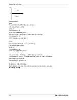
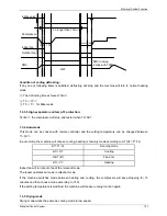
Page 65: ... Compressor is off 2 T3 TempEnterDefrost_ADD Time2 Time conditions Meet the following conditions 1 Running in heating mode 2 T4 3 3 Compressor is on 4 T3 TempEnterDefrost_ADD Cleared conditions Meet any one of the following conditions 1 Compressor is off and T3 TempEnterDefrost_ADD 2 last for 20 minutes 2 Running in cooling mode 3 Compressor is off for 1 hour Condition of entry defrosting time1 ti...

Page 66: ...T2 54 1 3 4 Auto mode This mode can be chosen with remote controller and the setting temperature can be changed between 17 30 In auto mode the machine will choose cooling heating or fan only mode according to T T T1 Ts T T1 Ts Running mode T 2 Cooling 1 T 2 Fan only T 1 Heating Indoor fan will run at auto fan of the relevant mode The louver operates same as in relevant mode If the machine switches...

Page 67: ...at low speed For floor standing the indoor fan is fixed at auto speed When heating the setting temperature decreases 1 be higher than 17 every one hour 2 hours later the setting temperature stops rising and indoor fan is fixed at low speed Anti cold wind function has the priority 1 3 7 3 Operation time in sleep mode is 7 hours After 7 hours the AC quits this mode but doesn t turns off 1 3 7 4 Time...

Page 68: ...nser pipe temp T3 If the temp is lower than 9 degree the digital display tube will show 9 If the temp is higher than 70 degree the digital display tube will show 70 If the indoor unit is not connected the digital display tube will show 08 Outdoor ambient temp T4 09 Compressor discharge temp T5 The display value is between 13 129 degree If the temp is lower than 13 degree the digital display tube w...

Page 69: ...it If the temp is lower than 0 degree the digital display tube will show 0 If the temp is higher than 70 degree the digital display tube will show 70 If the capacity demand is 0 the digital display tube will show 0 If the indoor unit is not connected the digital display tube will show heating T2 cooling T2B 20 Condenser pipe temp of 2 indoor unit 21 Condenser pipe temp of 3 indoor unit 22 1 Indoor...

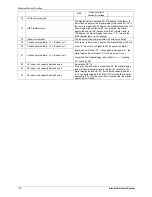
Page 70: ...r display board Ceiling Floor 2 1 3 Icon explanation on indoor display board A5 Duct OPERATION TIMER DEF FAN ALARM Temporary button Operation lamp Timer indicator Infrared signal receiver Alarm indicator PRE DEF indicator cooling and heating type or fan only indicator cooling only type MANUAL Display digital tube 2 1 4 Display board of auto lifting panel of 4 way cassette ...

Page 71: ...Troubleshooting 112 Electrical Control System 2 1 5 Display board of GA floor standing 2 1 6 Display board of M floor standing ...

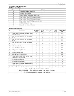
Page 72: ...Open or short circuit of T1 temperature sensor X X X E2 3 Open or short circuit of T2 temperature sensor X X X E3 4 Open or short circuit of T2B temperature sensor X X X E4 5 Full water malfunction X X X EE 6 Indoor EEPROM malfunction X X X E7 7 Refrigerant Leakage Detection O X EC 8 Outdoor unit malfunction X X X Ed 9 Indoor fan speed is out of control X X E8 10 Communication malfunction between ...

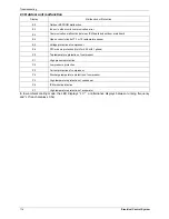
Page 73: ... E5 Voltage protection of compressor E6 PFC module protection Only for 48K with 1 phase P0 Top temperature protection of compressor P1 High pressure protection P2 Low pressure protection P3 Current protection of compressor P4 Discharge temperature protection of compressor P5 High temperature protection of condenser P6 IPM module protection P7 High temperature protection of evaporator In low ambien...

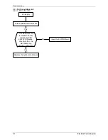
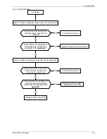
Page 74: ... indoor unit 2 4 1 1 Open or short circuit of temperature sensor Check the connections between temperature sensor and PCB Are the connections good Correct the connections No Yes Yes Replace indoor or outdoor PCB Replace the sensor Check the resistance value of the sensor via Appendix 1 Is it normal No ...

Page 75: ...No No Check whether the power is on Replace outdoor main board Yes Whether the outdoor unit is power on Check whether the communication wire between the indoor and outdoor unit is connected correctly Yes Connect the wiring well or replace the communication wire No Replace the indoor PCB Trouble is solved check if the errors happen again Yes No Outdoor unit malfunction ...

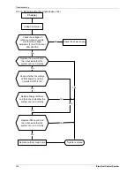
Page 76: ...EEPROM well Replace the indoor PCB Shut off the power supply and turn it on 5 seconds later Is it still displaying the error code 2 4 1 4 Full water malfunction If the water level switch is inserted well No Insert the water level switch well If the water level switch is broken Yes Replace the water level switch If the water pump is normal No Replace the water pump Yes No Yes Check PCB board or rep...

Page 77: ...eplace indoor fan motor Check the wires of fan motor Are all the connections good No Yes No Correct the connections No Yes Replace indoor main PCB Is it still displaying the error code Yes Yes Check the voltage between port 1 and 6 of fan motor connector is it 310V No DC motor voltage input and output control chip is inside the motor DC motor voltage input and output NO Color Signal Voltage 1 Red ...

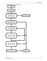
Page 78: ...equal to each other the fan motor must have problems and need to be replaced Otherwise go to step 2 2 Power on and when the unit is in standby measure the voltage of pin4 5 in feedback signal connector If the value is not 5V change the PCB Otherwise go to step 3 3 Rotate the fan by hand measure the voltage of pin1 5 pin 2 5 and pin 3 5 in feedback signal connector If any voltage is not positive vo...

Page 79: ...Troubleshooting 120 Electrical Control System 2 4 2 For the super slim cassette with up down panel 2 4 2 1 Communication error between indoor unit and up down panel 2 4 2 2 Up down panel is defective ...

Page 80: ...Troubleshooting Electrical Control System 121 2 4 2 3 Up down panel is not closed ...

Page 81: ... outdoor unit 2 4 3 1 E0 malfunction If the EEPROM chip is welded on PCB replace the PCB directly Otherwise check whether the EEPROM chip plugged in PCB well Yes No Yes Insert the EEPROM well Replace the outdoor main board Outdoor EEPROM malfunction E0 display ...

Page 82: ...ence Increase the capacity of anti interference Yes Yes Replace the signal wire Yes Pull out and insert back No No Replace indoor PCB is the error distinguished Yes Replace the outdoor PCB No Check whether there s any interference Such as too many lamps power transformers Or the signal wire is too long Check whether the signal wire is shield cable or whether the shield cable is earthing Check whet...

Page 83: ...d light Check the signal wire between the IPM module and the main board is it connected good Reconnect and retry Is error still display Replace IPM board and then check whether the system can run normally Replace the electric control box No No No No Yes Trouble is solved No Yes Replace outdoor main board and then check whether the system can run normally No Yes Yes E3 display ...

Page 84: ...er the resistance of condenser temp sensorT3 is wrong refer to the Appendix 1 Yes Connect the wiring well Yes Judge 2 Outdoor ambient temp sensor T4 is malfunction No Replace outdoor ambient temperature sensor T4 Check whether the wiring of the outdoor ambient temperature sensor T4 is broken off Check whether the resistance of outdoor ambient temperature sensor T4 is wrong refer to the Appendix 1 ...

Page 85: ...20 240VAC Check the power supply Check whether the voltage of IPM board P and N is normal DC277 410V Replace bridge rectifiers and then check whether the system can run normally Replace IPM board and then check whether the system can run normally Replace outdoor main board Yes No No No No Yes Trouble is solved Yes Yes E5 display Replace the power board then check whether the system can run normall...

Page 86: ...L 1 L 2 L 3 is about 380VAC Check the power supply Check whether the voltage range of P N on IPM module is normal DC 350 650V Replace bridge rectifiers and then check whether the system can run normally Replace IPM board and then check whether the system can run normally Replace outdoor main board Yes No No No No Yes Trouble is solved Yes Yes E5 display Replace the power board then check whether t...

Page 87: ...Troubleshooting 128 Electrical Control System 2 4 3 7 E6 malfunction Only for 48K with 1 phase ...

Page 88: ...Troubleshooting Electrical Control System 129 2 4 3 8 P0 malfunction ...

Page 89: ...Troubleshooting 130 Electrical Control System 2 4 3 9 P1 malfunction ...

Page 90: ...Troubleshooting Electrical Control System 131 2 4 3 10 P2 malfunction ...

Page 91: ...Troubleshooting 132 Electrical Control System 2 4 3 11 P3 malfunction ...

Page 92: ...charge temp is more than 115 C Check whether the wiring connection is right between compressor discharge temp sensor and PCB according to wiring diagrams Method Check whether the resistance of compressor discharge temp sensor is right refer to the Appendix 2 No Yes Yes Trouble is solved No Judge The discharge temp sensor is broken Check whether the refrigerant is leak Correct the wiring connection...

Page 93: ...dge 1 Check whether the outdoor ambient temperature is higher than 50 No Judge 3 The refrigerant pipe is blocked Let the refrigerant out then use the high pressure nitrogen or refrigerant to blow pipe vacuumize and charge the refrigerant again Yes Judge 2 Check whether the heat exchanger is dirty No Clean the heat exchanger Yes Replace outdoor main board Yes Check whether the resistance of condens...

Page 94: ... or not No No No Connect it well check ok or not Check whether the connecting line of the compressor is connected correctly or tightly Replace the IPM module check whether the system can work normally No No Replace the main board check whether the system can work normally No Replace the compressor check whether the system can work normally Yes Yes Check whether the lines in E part box are connecte...

Page 95: ...k or not No No No Connect it well check ok or not Check whether the connecting line of the compressor is connected correctly or tightly Replace the IPM module check whether the system can work normally No No Replace the main board check whether the system can work normally No Replace the compressor check whether the system can work normally Yes Yes Check whether the lines in E part box are connect...

Page 96: ...d and the indoor fan is running normal No Check refrigerant system such as clogging of capillary etc No Clean the heat exchanger and the air outlet Reconnect and retest No Whether the connection is good No Check the resistance value of the sensor via Appendix 1 Is it normal Check whether the indoor fan is running normal Replace the temperature sensor No Yes Whether the indoor PCB is normal Replace...

Page 97: ... 6 13059 76 1 34105 116 0 40060 3 41 5878 37 5 87359 77 1 29078 117 0 38991 2 39 8239 38 5 62961 78 1 25423 118 0 37956 1 37 1988 39 5 39689 79 1 21330 119 0 36954 0 35 2024 40 5 17519 80 1 17393 120 0 35982 1 33 3269 41 4 96392 81 1 13604 121 0 35042 2 31 5635 42 4 76253 82 1 09958 122 0 3413 3 29 9058 43 4 57050 83 1 06448 123 0 33246 4 28 3459 44 4 38736 84 1 03069 124 0 32390 5 26 8778 45 4 21...

Reviews: