


DS4-2499D
- 7 -
Aタイプ
Bタイプ
Bタイプ
Aタイプ
Aタイプ
Bタイプ
Bタイプ
Aタイプ
Aタイプ
Bタイプ
Aタイプ
Bタイプ
例 1 .
例 2 .
例 3 .
※2.反射物等がなければ干渉しません。
※1.データの干渉は起きませんが、受光量表示には互いに影響が出ます。
(光軸調整・光量確認時には、調整しない対の電源を切ってください。)
1.5m以上
3m
以上
※2
対向するAタイプ間の距離が近い場合には、
受光量表示に影響が出る場合があります。
その場合には、調整しない対の電源を切って調整してください。
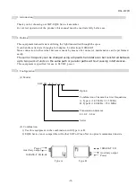
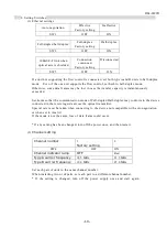
(3) Installation intervals
When plural transmitters are to be installed or a transmitter is used near another photoelectric
sensor, they shall be installed at sufficient intervals to prevent optical interference.
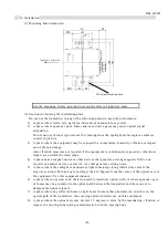
Note:
The optical axis deviation due to optical axis adjustment, vibration, impact, etc.
may affect the optical interference. When installing the equipment on a moving
carrier, check before use that the equipment can normally communicate throughout
the communication area after adjustment of the optical axis according to section 9
“Adjustment of the Optical Axis.”
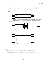
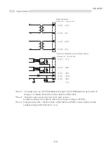
Example 1
Type A
Type A
Type B
Type B
0.
5 m
or
mo
re
3 m
or
m
o
re
Type A
Type A
Type A
Type A
Type B
Type B
Type B
Type B
*1. Though data interference does not occur, the display of light reception level may be affected mutually.
(In time of optical axis adjustment/optical level check, turn off the power of unadjusted couple.)
Example 2.
*2. If no reflecting object exists, no interference occurs.
Example 3.
*3.The interval as shown in Example 1 may be used if a different channel is used for each pair.