DS4-2499D
- 11 -
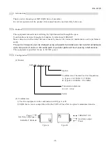
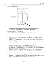
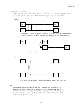
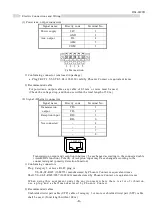
9. Adjusting of the Optical Axis
During the adjustment of optical axis, damaged data could come out of signal (Ethernet) connector.
Remove the cable from the connector, or make sure that there will be no problem if any damaged data
flows to the network, then start adjustment.
(1) After checking that wires have been correctly connected, turn on the power supply to the main unit.
The power indicator lamp (POW) shows red.
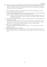
(2) Loosen the main unit mounting screws and move the main unit in the vertical and horizontal directions
until the clear data indicator lamp (CD) on the receiving unit shows red.
<Note> Reception levels at the receiving unit on the main unit will not be displayed if the own unit
reception level fails to be CD or more. First, adjust by referring to the display of reception
level on the receiving unit.
(3) Make further fine adjustment until the reception level indicator lamps on the receiving unit show green
up to LEVEL 3 or higher.
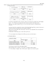
Detailed reception levels are checked by the tester connected to the check terminal of receiving unit.
Reception levels are measured by a tester (input resistance being 10 k
Ω
/V or higher in DC voltage
range 10V or so). Tester bars of
Φ
2 shall be inserted into (+) and (-) of check terminal.
(4) Max value of check terminal voltage is 4.2V or so.
In operation, fix at the position of max voltage by referring to 2.2V or higher in the case of the max
transmission distance.
(5) Adjust the receiving unit in the same manner.
(6) When installing either unit on a moving body such as a stacker crane, check that the reception level
indicator lamps up to LEVEL 3 or higher show green at both moving and fixed units across the moving
areas.


