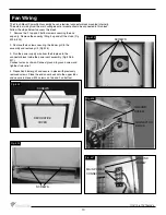
PRESSURE
SWITCH
LOW SIDE
OF SWITCH
HIGH SIDE
OF SWITCH
111011-16 TCVT.FMPV3
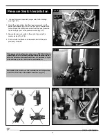
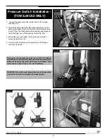
1. Connect the pressure switch jumper wires to the orange
wire (Fig. # 16).
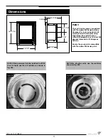
2. Attach the silicone tube from the upper pressure tap on the
power vent adaptor (Fig. #4) to the “low” port of the pressure
switch. Attach the other silicone tube from the lower pressure
tap to the “high” port of the pressure switch (Fig. #17).
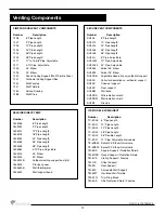
3. Secure the pressure switch in the control box using the
screw provided (Fig. #18).
4. Continue with installation and reassemble all of the parts
previously removed.
WARNING: This switch must be installed in a vertical position
and will not function if installed otherwise. (Fig. 16)
This power vent system can only run on 115 V AC. Before
operating the unit, the battery backup located behind the wall
switch receiver must be removed. The red “Low Battery” light
will continue to fl ash. This is not a fault indicator.
ORANGE WIRE
Fig. #16
Fig. #17
Fig. #18
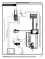
Fig. #18a
8
Pressure Switch Installation
Summary of Contents for TCVT.FMPV3
Page 15: ...111011 16 TCVT FMPV3 15 ...


