4. Replace each part to new ones.
5. Mount it in the reverse order of removal.
Notes:
• Check that the pad for T brake lever assembly and
compression spring (7) are attached.
When mounting the T brake lever assembly, do not
touch the pad to the T reel table.
• Before mounting the brake spring (1), check that the
S, T brake assemblies (2) and (3) move smoothly.
• When replacing the S brake assembly (4), do not
damage the band brake (8).
Fig. 1-6-28
4. Replace each part with new one.
5. After replacing, mount it in the reverse order of
removal.
Note:
• Check the reel torque by using a torque cassette.
(Performs when replacing the clutch gear assembly
and the idle lever assembly.)
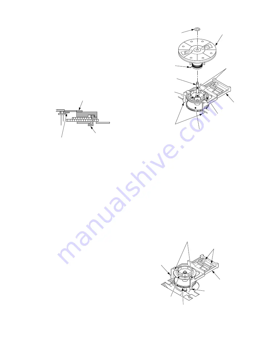
6. Mount the center gear assembly (1) and the Up/Down
lever assembly (2) together.
First, insert the claws (5) of the Up/Down lever
assembly (2) to the base and insert the center gear
assembly (1) to the center post (6) with the flange of
the center gear assembly (1) positioned lower than
the guide (8).
Idle lever
Hook surely to catch the base.
Insert the rotation center portion between the base
and the center post flange.
Fig. 1-6-27
1-6-10. Holder Clutch Assembly, Center Gear
Assembly and Up/Down lever Assembly
Replacement
1. When replacing the center gear assembly (1) and Up/
Down lever assembly (2), remove the S, T brake
assemblies and idle lever assembly (refer to item 1-6-
9) and cam slider (refer to Fig. 1-6-7) in advance.
2. Remove the stop ring (3) fixing the holder clutch
assembly (4) and remove the holder clutch assembly
(4).
3. Release two claws (5) of the Up/Down lever assembly
(2) from the mechanical deck and remove the Up/
Down lever assembly (2) with the center gear
assembly (1) attached.
Notes:
• After cleaning the center post (6) by using a cleaning
kit, apply oil to the upper portion of the center post
(6) drop by drop. (Performs when replacing the center
gear assembly (1) Up/Down lever assembly (2) and
the holder clutch assembly (4).)
• Apply grease to the center gear assembly (1) (Per-
forms when replacing the center gear assembly (1)
and the Up/Down lever assembly (2).)
Stop ring (3)
Holder clutch
assembly (4)
Spring
Apply a drop of oil
after cleaning.
Apply grease to both
sides of flange.
Center gear assembly (1)
Center post (6)
Claws (5)
Up/Down lever
assembly (2)
(Insert the groove A.)
Groove A
Guide (8)
Claw (10)
Claws (5)
Claw (9)
Flange (7)
Center gear
assembly (1)
Up/Down lever
assembly (2)
Fig. 1-6-29
Furthermore, push the parts downward until the
claws (9) and (10) of the Up/Down lever assembly (2)
catch the mechanical deck.


