background image

198

Ethernet module User’s Manual

Chapter 8 Error Handling

8

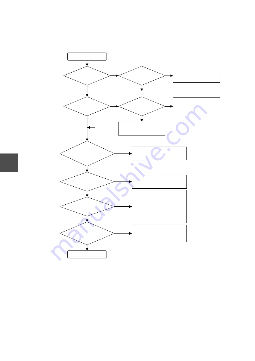
(7) When Transmission Using TCP Sockets Fails

When troubleshooting TCP sockets, also refer to the "TCP Socket Notes" section. 

(a) Open request


Start 

Refer to the completion status 
and eliminate the cause of the 
error. 

Is the URCV_T 

instruction completed ? 

A timeout occurred ?   

Error status --- 2848 

No 

Yes 

Yes 

Confirm the status when the 
USEND_T or URCV_T is not 
completed. 

Is the station status 

such that run + socket 

transmission is 

enabled ? 

Set the station to run + socket 
transmission enabled using an 
operating mode control request. 

Is the waiting time set 

to unlimited ? 

No 

No 

No 

Yes 

Yes 

① 

① 

End 

Verify the remote node IP address 
and UDP port number. 

1) Check the slave station IP address 

and message transmission UDP 
port number again. 

2) Configure the router if there is a 

router on the transmission line. 

3) Check the network verification 

items. 

Are the remote node   

IP address and UDP port 

number correct ? 

No 

Yes 

Decide which role each socket will 
play when establishing a connection 
between a pair of sockets. 

Is the program   

attempting to issue an active 

open to a socket in the passive 

open state ? 

No 

Yes 

No 

Yes 

Does a response come   

back if a PING is issued to the 

remote station ? 

No 

Yes 

Is the error counter   

read out from the RAS information 

constant ? 

RAS error counters: 

Alignment error 

Short packet,    CRC error 

It is possible that there is an error on 
the network itself. Check the network 
verification items. 

Summary of Contents for V Series

Page 1: ...6F8C0904 Integrated Controller V Series Ethernet module EN311 User s Manual Sep 30 2004 ...

Page 2: ...s book may be reproduced stored in a retrieval system or transmitted in any form or by any means electrical mechanical photocopying recording or otherwise without obtaining prior written permission from TOSHIBA Corporation PROSEC TOSLINE and TOSDIC are trademarks or registered trademarks of TOSHIBA Corporation IBM is a registered trademark of International Business Machines Corporation Microsoft M...

Page 3: ...ty damage means extended breakdown of assets and materials Notation of Markings Note The description of forbiddance mandatory and caution marks are subject to change depending on the labels on the main unit WARNING Indicates a potentially hazardous situation which if not avoided could result in serious injury or death CAUTION Indicates a potentially hazardous situation which if not a avoided can r...

Page 4: ...e is condensation due to sharp temperature variations Locations where the ambient temperature exceeds the allowance range Locations where the relative humidity exceeds the allowance range Locations where the equipment is exposed to direct sunlight Locations where strong electric radiation or magnetic field is generated Improper the installation or writing of the system can cause not only insuffici...

Page 5: ... the positive and negative polarities Failure to observe this could cause trouble 2 For module wiring either use crimp terminals with sheath or cover the wires with tape so that there will be no exposed conductors Handle the terminal board cover with care not to drop or break and place it securely on the terminal board after the wiring Exposed conductors could cause electric shook 3 It is recommen...

Page 6: ...n cause trouble or malfunction Forbidden 1 The EN311 cannot be simultaneously connected to 10BASE5 and 10BASE2 systems 2 Do not connect unused network cables to the EN311 Failure to observe this could cause trouble and or malfunction 3 Do not connect or disconnect cables when power T3H MAU supply power is on Failure to observe this could cause trouble and or malfunction Forbidden 3 Safety Precauti...

Page 7: ...s removed from the unit on a conductive mat or conductive bag containing a spare board etc on an grounded desk Otherwise static electricity can damage components of the module Mandatory Do not apply benzene and thinner when clean ing the equipment Otherwise it can cause deformity or discolora tion the panel or case of the equipment Forbidden Be careful not to hit or fall off the equipment by accid...

Page 8: ...rheat Forbidden Turn off power immediately if the ambient temperature or internal temperature exceeds beyond normal range or if failure is occurred in the equipment Contact Toshiba for repairing Operation under such situation can cause fire or electrical shock Mandatory Do not enter wire scrapes or other foreign debris into the equipment Also do not insert metal parts into them They can cause fire...

Page 9: ...isposing of the lithium battery or Ni Cd battery observe the rules and regulations of the local administration Mandatory 7 Precautions for Use of The Equipment 1 The emergency stop circuit interlock circuit etc must be laid out outside the S controller that includes EN311s If the S controller and or EN311s should develop trouble or malfunction it could cause an accident involving physical injuries...

Page 10: ... studied for applicability to an actual system Mandatory 1 The EN311 cannot be simultaneously connected to 10BASE5 and 10BASE2 systems Do not connect unused network cables to the EN311 Failure to observe this could cause trouble and or malfunction 2 Do not operate the 10BASE5 10BASE2 selector dual switches during data transmission or reception Otherwise it could cause trouble and or malfunction 3 ...

Page 11: ...systems of aviation and space systems and other systems and subsystems where safety is critical Note 3 Special care means to build a safety system foolproof design fail safe design redundancy design etc in full consultation with Toshiba s engineers Immunity Toshiba is not liable for any loss caused by fire earthquake action by a third party or other accidents or the operator s intentional or accid...

Page 12: ......

Page 13: ...red to operate the EN311 normally Chapter 4 Preparing for Operation Software Describes the software settings required to operate the EN311 normally and presents sample programs Chapter 5 Computer Link Protocol and the PC Link Protocol Transmission Gives the precautions describes the instruction format used with computer link protocol and PC link protocol transmission and presents sample programs C...

Page 14: ...xtremely humid place 3 If the ambient temperature of the internal temperature of the equipment has arisen too high or if the equipment has developed a fault stop using it switch power off and contact the nearest Toshiba service station 4 Do not open the case of the equipment while it is in operation except when setting the switches 5 Do not attempt to modify the equipment 6 To install wire use and...

Page 15: ...w to Setup 6F8C0873 Describes how to install the V Series Engineering Tools onto your PC Engineering Tools Basic 6F8C0875 Describes how to write debug print out and save the programs using the V Series Engineering Tools T Series Computer Link Operation Manual UM TS03 E008 Describes the specifications and handling of the computer link protocol transmission functions built into the V Series Controll...

Page 16: ......

Page 17: ...witch Settings 22 3 3 Mounting the EN311 in the Base Unit 23 3 4 Connecting to the Network 24 3 5 MAU Power Supply 27 3 6 Network Wiring Equipment 29 4 Preparing for Operation Software 31 4 1 Module Setup Flowchart Software 32 4 2 Registering the EN311 33 4 3 EN311 Operation Modes and Station Statuses 37 4 4 Function Block Specifications for EN311 Control 39 4 4 1 USED_T function block 39 4 4 2 UR...

Page 18: ... 3 Socket port numbers 96 6 2 4 General precautions for UDP TCP socket 96 6 2 5 UDP socket interface notes 97 6 2 6 Considerations for TCP socket 97 6 3 Socket Interface Information 100 6 4 Using the EN311 Socket Interface 102 6 4 1 UDP open request using the USEND_T instruction 103 6 4 2 UDP send request broadcast send request using the USEND_T instruction 104 6 4 3 UDP receive request using the ...

Page 19: ...et Interface Information 187 8 5 Troubleshooting 188 9 Installation and Wiring 205 9 1 Installation Environment and Base Unit Mounting 205 9 2 Mounting and Removing Modules 206 9 3 Power Supply Wiring and Grounding 207 9 4 Network Wiring 208 A Maintenance and Inspection 213 B Socket Service Command Table 215 C Error Status Table 217 D USEND_T and URCV_T Execution Times 221 E Computer Link PC Link ...

Page 20: ...CONTENTS xviii Ethernet module User s Manual G Change correction function in a firmware 231 G 1 Revision J 231 G 2 Revision K 233 G 3 Revision L 234 ...

Page 21: ...Cs and other programmable controller via the EN311 The EN311 can be connected to the LAN Local Area Network 10BASE5 Ethernet or 10BASE2 Cheapernet 10BASE5 or 10BASE2 can be selected by the switch on the module The following is a LAN configuration example using the EN311 In this example the S controller is connected to host machines such as workstations and personal computers over a 10BASE5 or 10BA...

Page 22: ...s should be used Also note that the data link layer of the EN311 send receive frame of the IP datagram adopts the DIX standard frame see Figure 6 8 The network terms used throughout this guide are the ones used in the ISO8802 3 standard The DIX standard terms colloquial terms and the ISO8802 3 standard network terms are mapped as follows Ethernet is a registered trademark of Xerox Corporation Chea...

Page 23: ... 9600001 and later If your product has a serial number prior to 9600001 but has I label attached to the end of the serial number it has been updated to revision I The number of digits in the serial number has changed to 8 from 7 since August 1999 Year month of manufacture 1999 June Month of manufacture Oct X Nov Y Dec Z How to read serial number 9 6 0 0 0 0 1 Reference number in the production lot...

Page 24: ...n the 10BASE5 2 LAN using the T series computer link protocol This function can be used simply by making basic settings on the EN311 from the S controller there is no need to write special user programs for the S controller Computer link protocol uses UDP IP as the transmission protocol UDP IP User datagram protocol Internet protocol Figure 1 2 T Series Computer Link Protocol Transmission slave st...

Page 25: ...e the host functions Only the basic EN311 settings performed from the T3H are required to use the slave functions and no special user programs are required on the T3H PC link protocol transmission uses UDP IP as the transmission protocol UDP IP User Datagram Protocol Internet Protocol Figure 1 3 T Series PC Link Protocol Transmission PC link host station PC link slave station User program Request ...

Page 26: ...e S controller and host machines is possible using the socket interface There are eight sockets on an EN311 and the transmission protocol TCP IP or UDP IP can be specified for each socket TCP IP Transmission Control Protocol Internet Protocol UDP IP User Datagram Protocol Internet Protocol Figure 1 4 Socket Interface Data transmission Host machine PC Workstation Application program 10BASE5 10BASE2...

Page 27: ...n data is routed to the default router One address IP address per router can be registered into EN311 The destination network must exist over this router To send data from an EN311 on Network A to a workstation on Network B the IP address of Router A should be registered into the EN311 If Router A is the EN311 router the EN311 cannot send data to any PCs on Network C To send data to PCs on Network...

Page 28: ...distance between MAUs 2 5 meters This network uses 50W coaxial cable as the transmission cable The EN311 can implement systems such as the one shown in the following figure using 10BASE5 coaxial cable Figure 1 7 10BASE5 Usage Recommendations Do not exceed the maximum cable length 500 m per segment or the maximum number of MAUs 100 in systems using 10BASE5 Adjacent MAUs must be mounted at least 2 5...

Page 29: ...coaxial cable as the transmission cable The EN311 can implement systems such as the one shown in the following figure using 10BASE2 coaxial cable Figure 1 8 10BASE2 Usage Recommendations Do not exceed the maximum cable length 185 m per segment or the maximum number of MAUs 30 in systems using 10BASE2 Adjacent nodes must be separated by at least 0 5 meter in systems using 10BASE2 10BASE2 coaxial ca...

Page 30: ...le with locking fitting BNC connector Connecting cable AUI cable conforming to the ISO8802 3 standard AUI cable up to 50 meters in length Coaxial cable RG 58 U with BNC connectors using T adapter Transmission services 1 T series computer link protocol slave station 2 T series PC link protocol master station slave station 3 Socket interface 8 sockets RAS functions 1 Self diagnostics at power on ROM...

Page 31: ...Mounting method In the Integrated Controller V Series parallel I O bus on model 3000 G3 bus Number of modules mountable 4 modules per unit USEND_T URCV_T function block module control and transmission functions Access method In case of installing the EN7 also 4 modules including EN7 per unit Table 1 2 Functional Specifications Item Specification Maximum distance between nodes Segment length Termin...

Page 32: ...nication circuit is first established and then data is transferred Packet order control retransmission flow control and other techniques guarantee transmission reliability The EN311 supports the following functions Response bit ACK Synchronized bit SYN Fin bit FIN Retransferring Window flow control Some functions have limitations Segment division Reporting of the maximum receivable segment length ...

Page 33: ...and receives data in the datagram format Sends data in datagram units to the remote node according to the IP address The EN311 supports the following functions Data fragmentation and reassemble Direct routing Broadcast Indirect routing Default routing The EN311 does not support the multicast functions Although the EN311 physical layer structure conforms to the ISO8802 3 standard it adopts DIX stan...

Page 34: ......

Page 35: ...6F8C0904 15 Chapter 2 EN311 Parts and Functions This chapter describes the sections of the EN311 and their functions ...

Page 36: ...16 Ethernet module User s Manual Chapter 2 EN311 Parts and Functions 2 2 1 Outline Drawing Figure 2 1 EN311 Outline Drawing ...

Page 37: ...imensions and Components Figure 2 2 EN311 Dimensions Front and Side Unit mm LED displays Reset switch Test connector 9 pin D SUB connector 10BASE2 connector 10BASE2 10BASE5 selection switch 10BASE5 connector LED display MAU power supply terminal block ...

Page 38: ... for AUI cables and the 10BASE5 connector and for AUI cable and the MAU 6 10BASE2 10BASE5 selection switch Switch for selecting what kind of network 10BASE5 or 10BASE2 the EN311 is connected to See section 3 2 Switch Settings for details on switching between 10BASE5 and 10BASE2 LANs 7 MAU power supply terminal block Terminal block for providing 12 V DC power to the 10BASE5 MAU and the EN311 intern...

Page 39: ...transmitted RCV Receive Green Indicates whether or not the module is receiving data from the transmission line On Data is present on the transmission line Off The transmission line is empty COL Collision red Indicates whether or not a collision is occurring on the transmission line during a data transmission On Collision s occurred Off No collisions occurred ACC Access Green Indicates whether or n...

Page 40: ......

Page 41: ...es Equipment can be damaged and breakdowns can be caused by operating this equipment incorrectly Start Set the 10BASE5 2 selection switch Mount the EN311 onto an S controller G3 I O bus Connect the EN311 to the network Select which LAN is to be used by setting the 10BASE5 10BASE2 selection switch See section 3 2 Switch Settings for details Mount the EN311 in an S controller G3 path and tighten the...

Page 42: ...e front panel to the right allows a 10BASE2 network to be connected Figure 3 3 Switch Settings when a 10BASE2 Network is Used front view Caution The EN311 cannot be connected to both a 10BASE5 and a 10BASE2 network concurrently Do not connect a network cable of the unused type to the EN311 This can damage the EN311 or cause it to malfunction Do not change this switch setting while a data transfer ...

Page 43: ...the section about the power supply capacity in the S3 User s Manual Hardware Caution The EN311 is designed specially for the V Series model 3000 and should only be mounted and used in a V Series model 3000 base unit Do not use this module independently or mounted in any other equipment Such usage could result in electric shocks personal injury or damage to the EN311 and other equipment The EN311 i...

Page 44: ...5 coaxial cable MAU and AUI cables Figure 3 4 AUI Cable Connection a Push the 10BASE5 connector sliding latch up b Align the AUI cable connector with the 10BASE5 connector and push it in c Push the 10BASE5 connector sliding latch down Make sure that the cable is locked and cannot be pulled out Caution The EN311 cannot be connected to both a 10BASE5 and a 10BASE2 network at the same time Do not con...

Page 45: ...applicable standards A qualified profes sional should perform installation and wiring See the ISO IEC 8802 3 standard for installation environment standards Usage Recommendations Do not exceed the maximum number of MAUs 100 or the maximum cable length 500 m in systems using 10BASE5 Adjacent MAUs must be mounted at least 2 5 meters apart in systems using 10BASE5 The AUI cable length must not exceed...

Page 46: ...ed and cannot be pulled apart Caution When installing a 10BASE5 or 10BASE2 network the cabling must be handled with ade quate safety precautions and in accordance with all applicable standards A qualified profes sional should perform installation and wiring See the ISO IEC 8802 3 standard for installation environment standards Usage Recommendations Do not exceed the maximum number of MAUs 30 or th...

Page 47: ...ed to Class D grounding 100W or less ground registance provided for the sole use of control equipment Such grounding is critical for reducing noise in the AUI cable Figure 3 6 shows the method used to provide this power Figure 3 6 Providing 12 VDC Power 1 DC 12V Power Unit Since an external power supply is not included with the EN311 installations will have to provide this equipment separately Sel...

Page 48: ...en providing a voltage to the MAU power supply terminal block always provide the cor rect 12 VDC voltage Any other voltage can damage the EN311 When wiring the module use either an insulated crimp type terminal or wrap conducting sec tions with insulating tape so that no conducting sections are exposed Be sure to handle the terminal block cover carefully so that it does not fall off or become dama...

Page 49: ...able MAU Catalog no EEA 9202 M TMJ x 2 Length Standard outer diameter 10 3 mm diameter with terminators at both ends Manufacturer Showa Electric Wire Cable Co Ltd Catalog no EPL 6213 Manufacturer Showa Electric Wire Cable Co Ltd Catalog no EEJ 6213 Manufacturer Showa Electric Wire Cable Co Ltd Catalog no EAD 6213 Manufacturer Showa Electric Wire Cable Co Ltd Catalog no EEL 6213 Manufacturer Showa ...

Page 50: ... Electric Wire Cable Co Ltd Catalog no ETS 8191 Manufacturer Showa Electric Wire Cable Co Ltd Catalog no EAD 8191 Manufacturer Showa Electric Wire Cable Co Ltd Catalog no EEJ 8191 Manufacturer Showa Electric Wire Cable Co Ltd Caution When installing a 10BASE5 or 10BASE2 network the cabling must be handled with ade quate safety precautions and in accordance with all applicable standards A qualified...

Page 51: ...ibes how to set up the EN311 software for operation Caution Make sure you understand the content of chapter 4 thoroughly before writing programs The sample programs present basic examples of EN311 usage and should be reviewed care fully before using them in an actual system ...

Page 52: ...N311 Turn on the controller power Press the reset switch Reset by a user program For details see section 4 5 Resetting the EN311 The EN311 parameters required for network transmission are set up by a user program running on the S controller In this state the system can handle remote station verification requests In this state the system can also respond to existence verification requests from othe...

Page 53: ... tool documentation 1 Starting the registration Select Station EN311TST from the Product View of the engineering tool then double click Station Configuration on the file list shown right Then the Configuration Editor starts and Hardware Configuration screen appears It is assumed that the main unit has been selected Main Unit BU742 model 3000 Main Unit Single Station Bus 2 slots G3 I O 9 slots Supp...

Page 54: ...4 Preparing for Operation Software 4 2 Connecting the module Example 1 Connect the EN311 to Slot 6 on the main unit Select Main Unit and select Connections in module Double click an empty slot to display the Module List Menu Double click here ...

Page 55: ...1 from the Module List Menu and click the Connect C button EN311 appears on Slot 6 of Hardware Configuration as shown in the following page EN311 appears in red at that time because the registration data has not been saved yet Similarly register the EN311 to Slot 7 Choose EN311 Click Connect C button ...

Page 56: ...the File menu and then the Save As command from the configuration editor menu to save the EN311 registration data The registration data is saved and the module name becomes black The registration of the EN311 has been completed If this is in red it has not been registered yet If it is in black it has been registered ...

Page 57: ...arameter the mode can be changed to Run mode by the S controller user program instruction 3 Run mode In this mode the EN311 can perform transmission with other nodes The mode can be changed to Standby mode by the S controller user program instruction In Run mode whether the computer link PC link procedure can be transmitted or not and whether the socket interface can be transmitted or not can be s...

Page 58: ...TBY Standby mode Standby mode Other than the Standby mode C RUN Run mode Run mode Other than the Run mode 5 MTEN Message transmission Permit Inhibit 4 STEN Socket I F transmission Permit Inhibit 0 TEST Test Test function being executed Test function complete or in waiting request state EN311 Mode Station Status Initialization being processed Power On Reset request Reset SW 4000H Standby mode Initi...

Page 59: ...nt to the EN311 4 4 1 USED_T function block 1 Parameters Supplementary information on input parameters Data structure of request command Communication FB Socket Communication Send Diagram Modification EN input Put into pulses Index modification Parameter Operand Type Constant Description Scope Input REQ Boolean Execution request CMD Pointer Request command P Pointer Beginning address of the transm...

Page 60: ...ON for one scanning time and the corresponding socket number is displayed on the STATUS When the transmission ends with an error the error ERROR becomes TRUE ON for one scanning time and the error status error description is displayed on the STATUS The completion output DONE does not turn ON if an error occurs Socket Service Commands used by USED_T Description Command Reset request 16 0311 Paramet...

Page 61: ...ONE becomes TRUE ON for one scanning time and the corresponding socket number is displayed on the STATUS Communication FB Socket Communication Send Diagram Modification EN input Put into pulses Index modification Parameter Operand Type Constant Description Scope Input REQ Boolean Execution request CMD Pointer Request command P Pointer Beginning address of the transmit data storage area N Unsigned ...

Page 62: ...16 0313 Sets the operating mode USEND_T 1 4 5 Remote station verification request 16 0314 Verifies the existence of another node on the network USEND_T 1 7 3 RAS information readout request 16 0315 Reads out the module RAS information URCV_T 1 7 5 Time set request 16 0318 Sets the module internal clock Time information for event trace USEND_T 1 7 4 Register read request PC link function 16 0321 Re...

Page 63: ...There are eight sockets and each can independently accept and execute Class 3 commands 5 If the S controller switches from the run to the halt state and then back to the run state while a command is being requested for the EN311 it is possible that the EN311 could execute the request issued immediately prior to the halt state This section describes the handling required after returning to the run ...

Page 64: ...a response is not received within the specified time from a remote station in a register read write request 5054 16 EC42 Memory write protect error Occurs if an attempt to store the SW register into the stor age area of the local reception data is made in the register read request 5074 16 EC2E Memory write protect error Occurs if an attempt to store the SW register into the stor age area of the re...

Page 65: ...ed in run mode in the socket interface transmission prohibited state Format error 70H Occurs when there is a format error in the request text 71H Port number error IP address error 72H Request code error 73H Time setting Year 74H Time setting Month 75H Time setting Day 76H Time setting Hour 77H Time setting Minute 78H Time setting Second Already opened 80H Occurs if an open request is issued for a...

Page 66: ...s is broadcasted on a remote station verification request MAC address specification error B0H BCC error B1H Occurs if an error occurs after address saving on a MAC setup request Insufficient resources error C0H Occurs if a transmission is repeated with cycle less than 100 ms to a non existent remote station for UDP send PC link transmission The UDP socket made the request to send when the buffer i...

Page 67: ...the down state EN311 module self check items System ROM check System RAM check LAN controller check Memory check for S controller interface See section 4 3 EN311 Operation Modes and Station Statuses for more information on the EN311 operating modes 1 S controller power on When power is applied to the S controller power is also applied to the EN311 and the EN311 performs its reset processing sequen...

Page 68: ...structure and error status Request command Error status Error status examples b Considerations A request can be issued if the EN311 is in run mode standby mode or down mode For TCP open request TCP receive request or UDP receive request if you use the request with unrestraint wait issue the reset request after changing the operation mode to the standby mode F 0 CMD Destination EN311 module slot nu...

Page 69: ...st be assigned to all nodes stations on the same i e any given network An IP address is a 32 bit data item IP addresses are written as the decimal values of each byte in the 32 bit datum with the decimal values separated by dots Example 11000000 00000000 00000000 00000001 192 0 0 1 IP addresses are divided into five classes A through C according to how many bits in the 32 bit value are used as the...

Page 70: ...o multiple subnets A subnet operates by taking some number of bits in the host address of the IP address for each class and using those bits as a subnetwork address This allows the installation to operate the network internally as multiple subnetworks while the network is recognized externally as a single network The subnet mask is used to determine how many bits of the host address to allocate as...

Page 71: ...d with the EN311 is from 1024 to 65535 for both TCP and UDP However note that the same port number cannot be used for both TCP and UDP on the EN311 This is because UNIX allocates port numbers 1 to 1023 for standard services The following section describes the format of the parameter setup request 4 Parameter setup request using the USEND_T instruction a Request command structure and error status R...

Page 72: ...EN311 S controller will process the received data in the order received and send the result from one of the message transmission send ports See Figure 4 4 Figure 4 4 Relationship between Message Transmission Send and Receive Port Numbers d Considerations The UDP port numbers used for message transmission must not duplicate UDP socket port numbers or TCP socket port numbers mentioned in the section...

Page 73: ...m the user program 1 Request command structure and error status Request command Error status Error status examples 2 IP address setup procedure F 0 CMD Destination EN311 module slot number CMD 1 Command 16 0319 CMD 2 Router IP address CMD 3 F 0 STATUS 0 Normal completion 0 Error status Error status number Description 5001 16 EC77 Command type error 5050 16 EC46 Module error Initialization in progr...

Page 74: ...up the local IP address to issue this request If this request is issued without setting the local IP address the following error will occur Error status MAC IP not set up 2896 16 B50 The following error occurs if the network address part of the local IP address dif fers from the router IP address Error status IP address error 2929 16 B71 Usage Recommendations For transmissions in case of connectin...

Page 75: ...MD 1 Command 16 0313 CMD 2 Specified information F 0 STATUS 0 Normal completion 0 Error status Error status number Description 5001 16 EC77 Command type error 5050 16 EC46 Module error Initialization in progress 2880 16 B40 Station mode error 2896 16 B50 MAC IP not set up 2929 16 B71 IP address error Bit Name Purpose D STBY standby request Switches the EN311 from run mode to standby mode C RUN run...

Page 76: ...equest specification 2947 16 B83 Simultaneous run mode and standby mode requests 30x0H cannot be executed Error status Incorrect control request specification 2947 16 B83 A mode that has already been established cannot be requested However requests that change the MTEN STEN state within the same mode do not cause an error Error status Incorrect control request specification 2947 16 B83 No executio...

Page 77: ...link Sample program specification EN311 is installed into Slot 6 on the base Local IP address 133 113 90 10 Local message transfer UDP port number 2000 Start Read the station status 7EFFH on DPRAM word address Run mode If the result of ANDing with 1000H is 1000H Issue the operating mode control request stand by Issue the reset request Issue the parameter setup request Issue the operating mode cont...

Page 78: ...status STBY_REQ BOOL PARA_REQ BOOL CMP_MODE BOOL ERR_MODE BOOL STS_MODE INT Standby request error status CMP_RESET BOOL ERR_RESET BOOL STS_RESET INT Reset request error status CMP_PARA BOOL ERR_PARA BOOL STS_PARA INT Parameter setup request error status CMP_MODE2 BOOL ERR_MODE2 BOOL STS_MODE2 INT Run request error status MREAD_CMP2 BOOL NOT_RUN BOOL RUN1 BOOL USEND_T_1 USEND_T USEND_T_2 USEND_T US...

Page 79: ...ECK MOVE_WORD 6 LD SLOTW ST OPEN_READ E T SLOTW LD MREAD TADDR 16 7EFF LD P STN_STS LD MREAD_CMP N 1 LD MREAD_CMP STN_STS LD AND_WORD 16 1000 LD STBY_REQ MREAD_CMPX S STN_STS ST STBY_REQ STN_STS LD EQ_WORD 16 1000 LD S PARA_REQ STN_STS LD NE_WORD 16 1000 LD PARA_REQ MREAD_CMPX ...

Page 80: ..._T USEND_T_1 P MW3 290 LD N MW3 290 LD S CMP_MODE S DONE STATUS STS_MODE ST ERROR ERR_MODE MOVE_WORD 6 LD 16 0313 LD MOVE_WORD MW3 310 ST MW3 311 ST MW3 312 ST 16 2000 LD MOVE_WORD CMP_MODE REQ CMD MW3 300 LD USEND_T USEND_T_2 P MW3 290 LD N MW3 290 LD S CMP_RESET S DONE STATUS STS_RESET ST ERROR ERR_RESET 6 LD MOVE_WORD MW3 300 ST MW3 301 ST 16 0311 LD MOVE_WORD ...

Page 81: ..._WORD MW3 320 ST MOVE_WORD MW3 321 ST 16 0312 LD PARA_REQ MOVE_WORD CMP_PARA REQ CMD MW3 310 LD USEND_T USEND_T_4 P MW3 290 LD N MW3 290 LD CMP_MODE2 S DONE STATUS STS_MODE2 ST ERROR ERR_MODE2 MOVE_WORD 6 LD 16 0313 LD MOVE_WORD MW3 310 ST MW3 311 ST MOVE_WORD MW3 312 ST 16 1010 LD NOT_RUN CMP_PARA REQ CMD MW3 310 LD USEND_T USEND_T_4 P MW3 290 LD N CMP_MODE2 DONE STATUS STS_MODE2 ST ERROR ERR_MOD...

Page 82: ...ion Software 4 STATION STATUS CHECK MOVE_WORD 6 LD SLOTW ST CMP_MODE2 E T SLOTW LD MREAD TADDR 16 7EFF LD P STN_STS LD MREAD_CMP2 N 1 LD STN_STS LD AND_WORD 16 1000 LD STN_STS ST NOT_RUN STN_STS LD NE_WORD 16 1000 LD S RUN1 STN_STS LD EQ_WORD 16 1000 LD MREAD_CMP2 ...

Page 83: ...ransmission from the host machine and PC link protocol transmission with the S controllers including S controller and T2N Caution Be sure to understand the contents of Chapter 5 thoroughly before writing programs The sample programs present basic examples of EN311 usage and should be reviewed care fully before use in an actual system ...

Page 84: ...ission and Operating mode control message transmission permission There is no need to create any special user programs on the S controller See the T Series Computer Link Operation Manual UM TS03 E008 for details on the functions specifications and usage of T series computer link protocol transmission Function Description 1 Reading the status Reads the status form the S controller 2 Reading the reg...

Page 85: ...omputer link protocol transmission This program issues a read write request for 32 words from the start of the S controller D registers Operating environment Hardware Toshiba J 3100PV PC AT compatible 3Com Etherlink III 3C509 B Software PC NFS Pro 1 1 1 0 Microsoft VisualC 1 0 Transfer parameters Local IP address 133 113 98 200 Local UDP port number 3001 Remote IP address 133 113 98 10 Remote UDP ...

Page 86: ...TOSHIBA Corporation 1995 All Rights Reserved Define declarations define MY_PORT 3001 Local port number define DST_PORT 3001 Remote port number define DST_IP 133 113 98 10 Remote IP address define LOOP 10 Data send receive execution counts define DATASIZ 32 Data size Computer link function word units define RECVTOUT 30 RECVFROM timeout time define REG_TYPE D Register type define REG_ADR 0000 Regist...

Page 87: ...sters Also note that registers in other stations can be accessed by modifying the SAMPLE H definition file C Copyright TOSHIBA Corporation 1995 All Rights Reserved Include declarations define WIN31 Windows 3 1 application define USECOMM COMM API is required include string h include stdio h include stdlib h include string h include memory h include sys types h include fcntl h include errno h includ...

Page 88: ...SAStartup wVersionRequested WsaDtata if ists 0 If normal return isdp socket AF_INET SOCK_DGRAM 0 Create socket UDP if isdp INVALID_SOCKET If normal return Soc sin_family AF_INET Soc sin_addr s_addr 0 Set local IP address Soc sin_port htons MY_PORT Set local port number Execute bind processing ists bind isdp struct sockaddr Soc sizeof Soc if ists SOCKET_ERROR If bind completed normally for i 0 i LO...

Page 89: ...imeout SELECT timer value struct sockaddr_in Snd Rcv iret 1 memset Snd 0x00 sizeof Snd memset Rcv 0x00 sizeof Rcv memset csnd 0x00 sizeof csnd Clear the send data buffer memset crcv 0x00 sizeof crcv Clear the receive data buffer Set up the register write send data sprintf csnd 0 A01DW Set up the register write command Set the starting register number sprintf csnd strlen csnd s REG_TYPE sprintf csn...

Page 90: ...ts recvfrom Isdp crcv sizeof crcv 0 struct sockaddr Rcv ircvsiz if ists 5 if crcv 4 C crcv 5 E crcv 4 E crcv 5 E return 1 Register write response error Register read request creation memset csnd 0x00 sizeof csnd memset crcv 0x00 sizeof crcv sprintf csnd 0 A01DR Register read command setup Set up the starting reg no sprintf csnd strlen csnd s REG_TYPE sprintf csnd strlen csnd 04s REG_ADR sprintf cs...

Page 91: ...otocol Program 5 Register read response reception ists recvfrom Isdp crcv sizeof crcv 0 struct sockaddr Rcv ircvsiz if ists 5 if crcv 6 C crcv 7 E iret 1 Register read response error else Register read response was normal iret 0 return iret ...

Page 92: ...ation EN311 message transmission UDP socket The user program that runs on the main station is discussed later When this function is used on the PC link slave station the S controller simply performs the following as described in Chapter 4 Parameter setup and Operating mode control message transmission permission There is no need to create any special user programs on the S controller Usage Recomme...

Page 93: ...ister type code CMD 3 DregNo Remote station register number CMD 4 TimeCnt Timeout time CMD 5 D IP address The input format is the same as that for parameter setup requests Remote station IP address CMD 6 CMD 7 D UDP PortNo Remote station message transmission UDP port number F 0 STATUS 0 Normal completion 0 Error status Error status number Description 5001 16 EC77 Command type error 5002 16 EC76 Ti...

Page 94: ...flags attached In case of T register you cannot specify the ranges spreading across the basic T 0 511 and expansion T 512 1023 DRegNo Remote station register number The remote station specifies the start register to which the transmission data is written TimeCnt Timeout value It is specified in 0 1 second unit to monitor the response time form the remote station RID Meaning RID Meaning 0000H XW YW...

Page 95: ...rite protection can be specified for each register type on the local S controller by using the special coil settings In this case a memory write protect error will occur For more information about this refer to the PROSEC T3H or T2N user s manual When PC link transmission is used if an application repeatedly transmits to a nonexistent remote station at short intervals less than 100 ms an insuffici...

Page 96: ... using the URECV_T instruction The register data specified by the remote station is read to the specified register on the local station 1 Request command structure and error status Request command Local station register is specified by the input operand P of the URCV_T function block Transfer register size is specified by the input operand N of the URCV_T function Specify in words 1 to 485 words T...

Page 97: ... completion 0 Error status Error status number Description 5001 16 EC77 Command type error 5002 16 EC76 Timeout detected by the S controller 2848 16 B20 Timeout detected by the EN311 Supplemental Remarks When the PC link is used and the EN311 detects an error it means that the error occurred in the local station if the highest bit of the error status shows 0 or it means that error occurred in the ...

Page 98: ...station controller scan operation If synchronization is necessary applications must perform synchroni zation such as transferring the data to separate registers at the start of the con troller scan When PC link transmission is used if an application repeatedly transmits to a nonexistent remote station at short intervals less than 100 ms an insufficient resources error may occur Applications should...

Page 99: ...irst D register 1500 Slot 7 First D register 1000 Slot 6 Local IP address 133 113 93 10 Local message transfer UDP port number 4002 Slot 7 Local IP address 133 113 93 154 Local message transfer UDP port number 4012 Start Issue a reset request Issue a parameter setup request Issue an operating mode control request run mode Start Issue a reset request Issue a parameter setup request Issue an operati...

Page 100: ...rror status CL_CMP2 BOOL CL_ERR2 BOOL CL_STS2 INT Slot 6 Run request error status CL_CMP3 BOOL CL_ERR3 BOOL CL_STS3 INT Slot 7 Parameter setup request error status CL_CMP4 BOOL CL_ERR4 BOOL CL_STS4 INT Slot 7 Run request error status X_COMPLETE1 BOOL TX_ERROR1 BOOL TX_REQ1 BOOL SND_STATUS1 INT Slot 6 Parameter setup request error status RX_COMPLETE1 BOOL RX_ERROR1 BOOL RX_REQ1 BOOL RCV_STATUS1 INT...

Page 101: ...ORD MW3 300 ST MW3 301 ST 16 0311 LD MOVE_WORD MW3 303 ST 7 LD MOVE_UINT MW3 302 ST RST_START REQ CMD MW3 300 LD USEND_T USEND_T_1 P MW3 300 LD N TX_CONT LD RST_CMP S RST_CMP S DONE STATUS RST_STS ST ERROR RST_ERR RST_CMP REQ CMD MW3 302 LD USEND_T USEND_T_2 P MW3 302 LD N TX_CONT LD RST_CMP2 S RST_CMP2 S DONE STATUS RST_STS2 ST ERROR RST_ERR2 ...

Page 102: ...W3 311 ST 4002 LD MOVE_UINT MW3 314 ST 16 8571_5D0A LD MOVE_DWORD MD3 312 ST RST_CMP2 REQ CMD MW3 310 LD USEND_T USEND_T_3 P MW3 310 LD N TX_CONT LD CL_CMP S CL_CMP S DONE STATUS CL_STS ST ERROR CL_ERR CL_CMP REQ CMD MW3 320 LD USEND_T USEND_T_4 P MW3 320 LD N TX_CONT LD CL_CMP2 S CL_CMP2 S DONE STATUS CL_STS2 ST ERROR CL_ERR2 MOVE_UINT 6 LD 16 0313 LD MOVE_WORD MW3 320 ST MW3 321 ST MOVE_WORD MW3...

Page 103: ...UINT MW3 334 ST 16 8571_5D9A LD MOVE_DWORD MD3 332 ST CL_CMP2 REQ CMD MW3 330 LD USEND_T USEND_T_5 P MW3 330 LD N TX_CONT LD CL_CMP3 S CL_CMP3 S DONE STATUS CL_STS3 ST ERROR CL_ERR3 CL_CMP3 REQ CMD MW3 340 LD USEND_T USEND_T_6 P MW3 340 LD N TX_CONT LD CL_CMP4 S CL_CMP4 S DONE STATUS CL_STS4 ST ERROR CL_ERR4 MOVE UINT 7 LD 16 0313 LD MOVE_WORD MW3 340 ST MW3 341 ST MOVE_WORD MW3 342 ST 16 1030 LD ...

Page 104: ...OVE_DWORD MW3 354 ST MD3 355 ST 100 LD MOVE_UINT MW3 358 ST 4012 LD MOVE_UINT MW3 357 ST MOVE_WORD 16 0201 LD 16 0403 LD MOVE_WORD MW3 500 ST MW3 501 ST 16 0807 LD MOVE_WORD MW3 503 ST 16 0605 LD MOVE_WORD MW3 502 ST MOVE_WORD 16 F9F8 LD 16 FBFA LD MOVE_WORD MW3 596 ST MW3 597 ST 16 FFFE LD MOVE_WORD MW3 599 ST 16 FDFC LD MOVE_WORD MW3 598 ST TX_REQ1 REQ CMD MW3 350 LD USEND_T USEND_T_7 P MW3 500 ...

Page 105: ...ST MW3 361 ST 1000 LD MOVE_UINT MW3 363 ST 4 LD MOVE_UINT MW3 362 ST MOVE_UINT 100 LD 16 8571_5D9A LD MW3 364 ST MD3 365 ST 100 LD MOVE_UINT MW3 368 ST 4012 LD MOVE_UINT MW3 367 ST RX_REQ1 REQ CMD MW3 360 LD URCV_T URCV_T_1 P MW3 1500 LD N MW3 368 LD S RX COMPLETE1 S DONE STATUS RCV_STATUS1 ST ERROR RX_ERROR1 RX_REQ1 TX_COMPLETE1 MOVE_DWORD ...

Page 106: ......

Page 107: ...TCP socket interface Next t this chapter presents notes on using the EN311 socket interface and describes the procedures for using this functionality Caution Make sure to understand the contents of this chapter thoroughly before writing programs that use the EN311 The sample programs present basic examples of EN311 usage and should be reviewed carefully before using them in an actual system ...

Page 108: ...Datagram Protocol Internet Protocol Figure 6 1 shows the positioning of the socket interface Figure 6 1 Positioning of the socket interface 2 Differences between the UDP socket interface and the TCP socket interface a UDP socket interface See Figure 6 2 Provides an in out port socket for data communication between a transmis sion source node and a transmission destination node Data for the transmi...

Page 109: ...odes one node must first open a socket in passive open mode and the other node must perform an active open on a local socket with respect to a remote socket that is in the passive open state Since the passive open socket node provides data transmission and other services it is called the server Since the active open socket node requests services it is called the client A socket for which a connect...

Page 110: ...equest Closed state Closed state Passive open Connection established Data reception Data reception Close request Closed state Connection establishment request Data transmission ACK acknowledge response Close request Close request Data reception Data reception Data transmission ACK acknowledge response Data transmission ACK acknowledge response Data transmission ACK acknowledge response ACK acknowl...

Page 111: ...itted data is divided into two fragments A with 1472 bytes and B with 528 bytes c A and B are put onto the transmission line d The receiving side EN311 connects the received data A and B restoring the original data e The data is accepted by a receive request from the receiving side S controller for 2000 bytes of data and the data is stored in the specified register see section 6 4 3 UDP receive re...

Page 112: ...800 1600 2400 3200 or 4000 bytes If the amount of received data is 800 or 1600 bytes those 800 or 1600 bytes can be acquired by a receive request from the S controller In cases where the amount of received data is 2400 3200 or 4000 bytes 2000 bytes will be transferred by the first receive request from the S controller and the remaining 400 1200 or 2000 bytes can be transferred by issuing another r...

Page 113: ...d by a receive request for 2000 bytes from the S controller and stored in the user specified register area see section 6 4 7 TCP receive request using the URCV_T instruction The amount of data that can be acquired by a TCP receive request differs depending on the timing with which the S controller issues the receive request and the timing with which the data arrives at the EN311 If data has not ye...

Page 114: ...ware on the receiving side must recognize the end of the transferred data either by using counts in the transmitted data or by including an end marker in the transmitted data and iterate receive requests until all the transmitted data has been received B does not arrive at the EN311 earlier than A through the TCP IP processing 11 User programs must store all incoming data so that the register area...

Page 115: ...s 0800H IP 0806H ARP IP header 20 bytes Packets UDP header 8 bytes flowing on the transmission line 72 1526 bytes IP datagram TCP header 20 bytes 46 1500 bytes Data field of IP data field The packet up to flowing on the 1480 bytes UDP data field up to 1472 bytes TCP data field up to 1460 bytes transmission line FCS Frame Check Sequence 4 bytes 32 bit CRC code for the sections of the packet other t...

Page 116: ...f time may be required to process some close requests 5 The EN311 includes a reception buffer of about 60 Kbytes to hold data addressed to the local station Since a TCP socket can receive up to a maximum of 5 840 bytes of data it is impossible even for eight TCP sockets to fill up this buffer which is 60K bytes With UDP sockets there is no limit on the receive data quantity per socket therefore in...

Page 117: ... remote node transmissions Number of remote nodes 50 ms 6 2 5 UDP socket interface notes 1 In transmission using UDP sockets the user program must implement any processing required to assure transmission reliability such as verifying the reception of transmitted data and retransmission 2 It is possible to broadcast to all nodes on the network using UDP sockets It is convenient to prepare a dedicat...

Page 118: ...he open request should be issued after waiting at least 10 seconds to open again with the same port number even the S controller close request had been completed normally If the open request is issued within 10 seconds using the same port number an error will occur 10 The EN311 in the current state does not support a keep alive function for TCP connections Verification from the EN311 side to other...

Page 119: ...recommended to reestablish the connection after closing it Window size The technique used to notify the available space in the receive buffer of the local socket to the remote socket It is possible that the window size becomes smaller because the receive data has not been processed for some reason or other 15 When the EN311 receives a segment with the reset bit RST set to 1 reset segment the RCLOS...

Page 120: ...et status has the following structure The conditions for each bit to become 1 as well as those for becoming 0 are listed in Table 6 2 Table 6 1 Socket Interface Information Storage Address Word Address Socket identifier 1 2 3 4 Remote node port number TCP only 16 7E43 16 7E4B 16 7E53 16 7E5B Remote node IP address TCP only 16 7E44 16 7E45 16 7E4C 16 7E4D 16 7E54 16 7E55 16 7E5C 16 7E5D Local node ...

Page 121: ...The socket closed in response to a close request C POPEN TCP socket in passive open state or UDP socket in open state The socket closed in response to a close request B CONN Disconnected by the local node with a close request Disconnected by the remote node A RCV Received text present No received text 9 RCLOSE An established TCP connection disconnected by the remote node The socket closed in respo...

Page 122: ...st close request TCP socket open request send request receive request close request Even when performing transmission by using the socket it is necessary to set the module of the EN311 in the same manner as the computer link PC link procedure transmission Caution Make sure to understand the contents of this chapter thoroughly before writing programs that use the EN311 The sample programs present b...

Page 123: ...t number on the local station not overlap with UDP port numbers used for message transmission and previously used UDP port numbers but it also must not overlap with any TCP port number An error will occur if the port number overlaps Error status Already open 2944 16 B80 If the S controller internal completion wait time limit 2 seconds is exceeded for this request the error listed below is returned...

Page 124: ...n error is returned if a socket identifier other than 1 to 8 is specified Error status Invalid socket identifier 2946 16 B82 If the IP address of the local node is specified as the transmission destination IP address it will be possible to send data but it will not be possible to receive that data with a receive request F0 CMD Request destination EN311 module slot number CMD 1 Command 16 0332 CMD ...

Page 125: ...socket 1 is activated frequently may not be able to process socket 8 resulting in the following error response Error status Send completion timeout 5002 16 EC76 When constructing a system take the socket utilization conditions into account when allocating sockets Since the send receive processing for each socket requires about 50 ms applications that issue send or receive requests to a given socke...

Page 126: ...rror status Error status examples 3 Request command details Receive data length Set this parameter to a value greater than or equal to the largest size for transmission data that could be sent to the object socket in a single operation Receive wait timeout time Specified in 0 1 second units 1 to 65535 If zero is specified the system is set to an unlimited infinite wait state F 0 CMD Request destin...

Page 127: ...65535 can be specified as the object socket UDP port number for the transmission source An error will be returned if a value outside that range is specified Error status Port number error 2929 16 B71 An error will be returned if a value of 0 words or 1001 or more words is specified as the receive data size Error status Transmission word count error 5059 16 EC3D An error will be returned if the rec...

Page 128: ...ived on the socket If the received data has different transmission source IP address and transmission source object socket UDP port number the data will not be transferred to the S controller If there are three received data packets on the EN311 UDP socket assuming all of the source sockets are different and the specified transmission source IP address and transmission source object socket UDP por...

Page 129: ... in an error being returned if an unlimited wait state UDP receive request is terminated with this request Error status Transmission completion timeout 5002 16 EC76 If the S controller internal completion wait time limit 2 seconds is exceeded for this request the error listed below is returned Error status Send completion timeout 5002 16 EC76 In this case first verify that the module is not in the...

Page 130: ...us Already open 2944 16 B80 An error is returned if a value other than 1 to 8 is specified as the socket identifier Error status Invalid socket identifier 2946 16 B82 An error will be returned if a value outside the range 1024 to 65535 is specified for the local node specified socket TCP port number Error status Port number error 2929 16 B71 F 0 CMD Request destination EN311 module slot number CMD...

Page 131: ...though there will be no error even if you set the timeout time to 32 seconds or more do not set the timeout time to unlimited infinite If you do so the socket remains to be waiting for active open when no connection is established within 32 seconds from the request In this case if you issue a close request to the object socket the open waiting state is released and the socket will be able to accep...

Page 132: ...data size Error status Transmission word count error 5059 16 EC3D The S controller performs an area check for the register area based on the transmission data storage register type and number and if an error is found it returns an error Error status Boundary error 5060 16 EC3C If a close request from the remote node TCP socket has arrived while a connection is established and the user program issu...

Page 133: ...e EN311 The TCP send request data size which is requested by the S controller is larger the window size of the remote node the EN311 will return an error Once it enters this state TCP send requests will repeatedly cause errors unless the remote node itself notifies the window size expansion In this case it is recommended to reestablish the connection after closing it Error status Remote node windo...

Page 134: ...data has been received by the socket Set the amount of data to be transferred to the S controller Reception wait timeout time specified in 0 1 second units 1 to 65535 If zero is specified the system is set to an unlimited infinite wait state 4 Methods for storing reception data The value specified as number of received data words N is the size of the transmitted data in a single operation to the s...

Page 135: ...ied Amount of data received by the socket the number of data words received N 1 Then only the reception data size of the received data from the beginning will be transferred to the S controller The remaining data will be stored in the EN311 Issue another receive request to receive the remaining data For a TCP receive request if the following condition is satisfied Amount of data received by the so...

Page 136: ...iving side as single units as well the user software on the receiving side must recognize the end of the transferred data either by using counts in the transmitted data or by detecting the end mark included in the transmitted data and iterate receive requests User programs must save all incoming data so that the register area used to transfer data to the S controller is not overwritten when using ...

Page 137: ... error being returned if an unlimited wait state TCP open request receive request is terminated with this request Error status Transmission completion timeout 5002 16 EC76 If the S controller issues the TCP close request to the EN311 the EN311 sends the connection end request FIN at the TCP level to the remote node At this stage the EN311 replies the completion of the close request to the S contro...

Page 138: ...ain with the same port number even the S controller completed the close request If the open request is issued within 20 seconds using the same port number the following error is returned Error status Already open 2944 16 B80 or Error status LAN controller driver error 2960 16 B90 2962 16 B92 When the remote station sends the end request after more than 10 seconds have elapsed since the EN311 sent ...

Page 139: ...stered as separate program Transmission is performed via Slot 6 Socket 1 Port number 3000 Open Æ Send Æ Close Reception is performed via Slot 7 Socket 1 Port number 3001 Open Æ Send Æ Close Socket status address of Socket 1 16 7E47 word address 1 Initialization routine Slot 6 Local station IP address 133 113 90 10 Local station message transmission UDP port number 3000 Slot 7 Local station IP addr...

Page 140: ...n status 7EFFH on DPRAM word address Run mode Is the result of ANDing 1000H is 1000H Issue the operating mode control request Standby Issue the reset request Issue the parameter setting request Issue the operating mode control request Run Read the station status Requested operating mode End Y Y N N ...

Page 141: ...on Start Sending side Read the socket status Are bits C and D 0 Issue the UDP open request Issue the UDP send request Issue the UDP close request End Sending side Y N Stop Normal completion N Stop N Y Y N Y Stop Stop Normal completion Normal completion ...

Page 142: ..._MODE INT Standby request error status CMP_RESET BOOL ERR_RESET BOOL STS_RESET INT Reset request error status CMP_PARA BOOL ERR_PARA BOOL STS_PARA INT Parameter setup request error status CMP_MODE2 BOOL ERR_MODE2 BOOL STS_MODE2 INT Run request error status MREAD_CMP2 BOOL NOT_RUN BOOL RUN1 BOOL MREAD_CMP3 BOOL OK_STS BOOL OPEN_CMP BOOL OPEN_ERR BOOL OPEN_STS INT UDP open request error status TX_RE...

Page 143: ...SEND_T USEND_T_7 USEND_T END_VAR b Program STATION STATUS CHECK MOVE_WORD 6 LD SLOTW ST OPEN_READ E T SLOTW LD MREAD TADDR 16 7EFF LD P STN_STS LD MREAD_CMP N 1 LD MREAD_CMP STN_STS LD AND_WORD 16 1000 LD STBY_REQ MREAD_CMPX S STN_STS ST STBY_REQ STN_STS LD EQ_WORD 16 1000 LD S PARA_REQ STN_STS LD NE_WORD 16 1000 LD PARA_REQ MREAD_CMPX ...

Page 144: ..._T USEND_T_1 P MW3 290 LD N MW3 290 LD S CMP_MODE S DONE STATUS STS_MODE ST ERROR ERR_MODE MOVE_WORD 6 LD 16 0313 LD MOVE_WORD MW3 310 ST MW3 311 ST MW3 312 ST 16 2000 LD MOVE_WORD CMP_MODE REQ CMD MW3 300 LD USEND_T USEND_T_2 P MW3 290 LD N MW3 290 LD S CMP_RESET S DONE STATUS STS_RESET ST ERROR ERR_RESET 6 LD MOVE_WORD MW3 300 ST MW3 301 ST 16 0311 LD MOVE_WORD ...

Page 145: ...MW3 320 ST MOVE_WORD MW3 321 ST 16 0312 LD PARA_REQ MOVE_WORD CMP_PARA REQ CMD MW3 310 LD USEND_T USEND_T_4 P MW3 290 LD N MW3 290 LD CMP_MODE2 S DONE STATUS STS_MODE2 ST ERROR ERR_MODE2 MOVE_WORD 6 LD 16 0313 LD MOVE_WORD MW3 310 ST MW3 311 ST MOVE_WORD MW3 312 ST 16 1010 LD NOT_RUN CMP_PARA REQ CMD MW3 310 LD USEND_T USEND_T_4 P MW3 290 LD N CMP_MODE2 DONE STATUS STS_MODE2 ST ERROR ERR_MODE2 MOV...

Page 146: ...ommunication 6 STATION STATUS CHECK MOVE_WORD 6 LD SLOTW ST CMP_MODE2 E T SLOTW LD MREAD TADDR 16 7EFF LD P STN_STS LD MREAD_CMP2 N 1 LD STN_STS LD AND_WORD 16 1000 LD STN_STS ST NOT_RUN STN_STS LD NE_WORD 16 1000 LD S RUN1 STN_STS LD EQ_WORD 16 1000 LD MREAD_CMP2 ...

Page 147: ...SOCKSTS LD MREAD_CMP3 N 1 LD SOCKSTS LD AND_WORD 16 3000 LD SOCKSTS ST S OK_STS SOCKSTS LD EQ_WORD 0 LD MREAD_CMP3 OK_STS REQ CMD MW3 330 LD USEND_T USEND_T_5 P MW3 290 LD N MW3 290 LD S OPNE_CMP S DONE STATUS OPEN_STS ST ERROR OPEN_ERR 1 LD MOVE_WORD MW3 332 ST MOVE_UINT MW3 333 ST 3000 LD 6 LD MOVE_UINT MW3 330 ST MOVE_WORD MW3 331 ST 16 0331 LD ...

Page 148: ...003 ST 16 6655 LD MOVE_WORD MW3 1002 ST MOVE_WORD 16 AA99 LD MW3 1004 ST MOVE_WORD 16 AAAA LD 16 BBBB LD MOVE_WORD MW3 1094 ST MW3 1095 ST MOVE_WORD MW3 1097 ST 16 CCCC LD MOVE_WORD MW3 1096 ST MOVE_WORD 16 EEEE LD MW3 1098 ST 16 DDDD LD OPEN_CMP2 REQ CMD MW3 340 LD USEND_T USEND_T_6 P MW3 1000 LD N MW3 999 LD S TX_CMP S DONE STATUS TX_STS ST ERROR TX_ERR OPEN_CMP2 OPEN_CMP TX_CMP REQ CMD MW3 360 ...

Page 149: ...Read the socket status Are bits C and D 0 Issue the UDP open request Read the socket status Issue the UDP receive request End Receiving side Y N Stop Normal completion N Stop N Y Y N Y Stop Stop Normal completion Normal completion Is bit A 1 N Y Issue the UDP close request ...

Page 150: ...uest error status CMP_RESET BOOL ERR_RESET BOOL STS_RESET INT Reset request error status CMP_PARA BOOL ERR_PARA BOOL STS_PARA INT Parameter setup request error status CMP_MODE2 BOOL ERR_MODE2 BOOL STS_MODE2 INT Run request error status MREAD_CMP2 BOOL NOT_RUN BOOL RUN1 BOOL MREAD_CMP3 BOOL OK_STS BOOL OPEN_CMP BOOL OPEN_ERR BOOL OPEN_STS INT UDP open request error status MREAD_CMP4 BOOL OK_OPEN BO...

Page 151: ...D_T USEND_T_2 USEND_T USEND_T_3 USEND_T USEND_T_4 USEND_T USEND_T_5 USEND_T URCV_T_1 URCV_T USEND_T_6 USEND_T END_VAR b Program STATION STATUS CHECK MOVE_WORD 7 LD SLOTW ST OPEN_READ E T SLOTW LD MREAD TADDR 16 7EFF LD P STN_STS LD MREAD_CMP N 1 LD S ...

Page 152: ... STBY REQ MREAD_CMPX S STN_STS ST STBY_REQ STN_STS LD EQ_WORD 16 1000 LD S PARA_REQ STN_STS LD NE_WORD 16 1000 LD PARA_REQ MREAD_CMPX MOVE_WORD 7 LD 16 0313 LD MOVE_WORD MW3 410 ST MW3 411 ST MOVE_WORD MD3 412 ST 16 2000 LD STBY_REQ REQ CMD MW3 410 LD USEND_T USENT_T_1 P MW3 290 LD N MW3 290 LD S CMP_MODE S DONE STATUS STS_MODE ST ERROR ERR_MODE ...

Page 153: ... S DONE STATUS STS_RESET ST ERROR ERR_RESET MOVE_WORD 7 LD 16 0311 LD MOVE_WORD MW3 400 ST MW3 401 ST S MOVE_WORD 7 LD 16 0312 LD MOVE_WORD MW3 420 ST MW3 421 ST 2001 LD MOVE_UINT MW3 424 ST 16 8571_5A14 LD MOVE_DWORD MD3 422 ST CMP_RESET REQ CMD USEND_T USEND_T_3 P N MW3 290 LD S CMP_PAPA DONE STATUS STS_PAPA ST ERROR ERR_PAPA PAPA_REQ MW3 290 LD MW3 420 LD ...

Page 154: ...W3 290 LD NOT_RUN CMP_MODE2 DONE STATUS STS_MODE2 ST ERROR ERR_MODE2 MOVE_WORD 7 LD 16 0313 LD MOVE_WORD MW3 410 ST MW3 411 ST MOVE_WORD MW3 412 ST 16 1010 LD MOVE_WORD 7 LD SLOTW ST CMP_MODE2 E T SLOTW LD MREAD TADDR 16 7EFF LD P STN_STS LD S MREAD_CMP2 N 1 LD STN_STS LD AND_WORD 16 1000 LD STN_STS ST NOR_RUN STN_STS LD NE_WORD 16 1000 LD STN_STS LD EQ_WORD 16 1000 LD MREAD_CMP2 RUN1 S ...

Page 155: ...SOCKSTS LD MREAD_CMP3 N 1 LD OK_STS SOCKSTS LD AND_WORD 16 3000 LD SOCKSTS ST SOCKSTS LD EQ_WORD 0 LD MREAD_CMP3 S OK_STS MOVE_UNIT 7 LD 16 0331 LD MOVE_WORD MW3 430 ST MW3 431 ST MOVE_WORD MW3 432 ST 1 LD MOVE_UNIT MW3 433 ST 3001 LD REQ CMD MW3 430 LD USEND_T USEND_T_5 P MW3 290 LD N MW3 290 LD S DONE STATUS OPEN_STS ST ERROR OPEN_ERR S OPEN_CMP ...

Page 156: ...DDR 16 7E47 LD P SOCKSTS LD MREAD_CMP4 N 1 LD SOCKSTS LD AND_WORD 16 0400 LD SOCKSTS ST OK_OPEN SOCKSTS LD EQ_WORD 16 0400 LD NOT_OPEN SOCKSTS LD NE_WORD 16 0400 LD MREAD_CMP4 1 LD MOVE_WORD MW3 452 ST MW3 453 ST 16 8571_5A0A LD 7 LD MOVE_UINT MW3 450 ST MW3 451 ST 16 0333 LD 101 LD MOVE_UINT MW3 2999 ST 3000 LD MOVE_UINT MW3 455 ST MW3 456 ST 0 LD MOVE_WORD MOVE_DWORD MOVE_WORD ...

Page 157: ...RCV_T URCV_T_1 P MW3 3000 LD N MW3 2999 LD S RX_CMP S DONE STATUS RX_STS ST ERROR RX_ERR RX_CMP REQ CMD MW3 460 LD USEND_T USEND_T_6 P MW3 290 LD N MW3 290 LD S CLOSE_CMP S DONE STATUS CLOSE_STS ST ERROR CLOSE_ERR 16 0334 LD MOVE_WORD MW3 461 ST MW3 462 ST 1 LD MW3 460 ST 7 LD MOVE_UINT MOVE_UINT ...

Page 158: ...00 Active open timeout is 30 seconds Æ Send Æ Close first Reception is performed via Slot 7 Socket 1 Port number 4001 Passive open timeout is 30 seconds Æ Receive Æ Close when RCLOSE is set to 1 Number of send receive words 100 words Socket status address of Socket 1 16 7E47 word address 1 Initialization routine Slot 6 Local station IP address 133 113 90 10 Local station message transmission UDP p...

Page 159: ...AM word address Run mode Is the result of ANDing 1000H is 1000H Issue the operating mode control request Standby Issue the reset request Issue the parameter setting request Issue the operating mode control request Run Read the station status Requested operating mode End Y Y N N ...

Page 160: ...P transmission Start Sending side Read the socket status Are bits C and D 0 Issue the TCP open request Active Issue the TCP send request Issue the TCP close request End Sending side Y N Stop Normal completion N Stop N Y Y N Y Stop Stop Normal completion Normal completion Timeout N Y ...

Page 161: ...RESET BOOL ERR_RESET BOOL STS_RESET INT Reset request error status CMP_PARA BOOL ERR_PARA BOOL STS_PARA INT Parameter setup request error status CMP_MODE2 BOOL ERR_MODE2 BOOL STS_MODE2 INT Run request error status MREAD_CMP2 BOOL NOT_RUN BOOL RUN1 BOOL MREAD_CMP3 BOOL OK_STS BOOL OPEN_REQ BOOL OPEN_REQ2 BOOL OPEN_CMP BOOL OPEN_ERR BOOL OPEN_STS INT TCP open request error status TX_REQ BOOL TX_CMP ...

Page 162: ...tion 6 USEND_T_1 USEND_T USEND_T_2 USEND_T USEND_T_3 USEND_T USEND_T_4 USEND_T USEND_T_5 USEND_T USEND_T_6 USEND_T USEND_T_7 USEND_T END_VAR b Program STATION STATUS CHECK MOVE_WORD 6 LD SLOTW ST OPEN_READ E T SLOTW LD MREAD TADDR 16 7EFF LD P STN_STS LD MREAD_CMP N 1 LD ...

Page 163: ...S STN_STS ST STBY_REQ STN_STS LD EQ_WORD 16 1000 LD S PARA_REQ STN_STS LD NE_WORD 16 1000 LD PARA_REQ MREAD_CMPX STBY_REQ REQ CMD MW3 310 LD USEND_T USEND_T_1 P MW3 290 LD N MW3 290 LD S CMP_MODE S DONE STATUS STS MODE ST ERROR ERR_MODE MOVE_WORD 6 LD 16 0313 LD MOVE_WORD MW3 310 ST MW3 311 ST MW3 312 ST 16 2000 LD MOVE_WORD ...

Page 164: ...3 290 LD N MW3 290 LD MOVE_WORD 16 0311 LD MW3 301 ST ERR_MODE USEND_T_2 DONE ERROR STATUS STS_RESET ST S CMP_RESET S ERR_RESET CMP_RESET PARA_REQ MOVE_WORD 6 LD 16 0312 LD MOVE_WORD MW3 320 ST MW3 321 ST MOVE_DWORD MW3 322 ST 16 85715ADA LD MOVE_WORD MW3 324 ST 2000 LD S CMP_PARA S ERR_PARA REQ CMD MW3 320 LD USEND_T P MW3 290 LD N MW3 290 LD USEND_T_3 DONE ERROR STATUS STS_PARA ST ...

Page 165: ... DONE ERROR STATUS STS_MODE2 ST MOVE_WORD 6 LD 16 0313 LD MOVE_WORD MW3 310 ST MW3 311 ST MW3 312 ST 16 1010 LD CMP_PARA NOT_RUN MOVE_WORD CMP_MODE2 MOVE_WORD 6 LD SLOTW ST E T SLOTW LD MREAD TADDR 16 7EFF LD P STN_STS LD MREAD_CMP2 N 1 LD STN_STS LD AND_WORD 16 1000 LD STN_STS ST NOT_RUN STN_STS LD NE_WORD 16 1000 LD S RUN1 STN_STS LD EQ_WORD 16 1000 LD MREAD_CMP2 ...

Page 166: ... Socket Interface Communication 6 SOCKET STATUS CHECK SOCKET 1 MOVE_WORD 6 LD SLOTW ST RUN1 E T SLOTW LD MREAD TADDR 16 7E47 LD P SOCKSTS LD MREAD_CMP3 N 1 LD SOCKSTS LD AND_WORD 16 3000 LD SOCKSTS ST S OK_STS SOCKSTS LD EQ_WORD 0 LD MREAD_CMP3 ...

Page 167: ...PNE_CMP DONE STATUS OPEN_STS ST ERROR 1 LD MOVE_WORD MW3 632 ST MW3 633 ST 1 LD 6 LD MOVE_UINT MW3 630 ST MW3 631 ST 16 0335 LD 4000 LD MOVE_UINT MW3 637 ST MW3 638 ST 300 LD 16 8571_5A14 LD MOVE_DWORD MW3 634 ST MW3 636 ST 4001 LD OK_STS OPEN_REQ OPEN_REQ2 MOVE_UINT MOVE_UINT MOVE_WORD MOVE_WORD OPEN_REQ OPEN_STS LD EQ_INT 16 0B20 LD OPEN_ERR ...

Page 168: ... MW3 1002 ST MOVE_WORD 16 5555 LD MW3 1004 ST MOVE_WORD 16 BBBB LD 16 CCCC LD MOVE_WORD MW3 1095 ST MW3 1096 ST 16 EEEE LD MOVE_WORD MW3 1098 ST 16 DDDD LD MOVE_WORD MW3 1097 ST MOVE_WORD 16 FFFF LD MW3 1099 ST S TX_CMP REQ CMD MW3 640 LD USEND_T P MW31000 LD N MW3 999 LD USEND_T_6 DONE ERROR STATUS TX_STS ST OPEN_CMP S TX_ERR MOVE_UNIT 6 LD 16 0339 LD MOVE_WORD MW3 660 ST MW3 661 ST MOVE_UNIT MW3...

Page 169: ...nd D 0 Issue the TCP receive request End Receiving side N Stop N N Y Stop Stop Normal completion Normal completion Is bit A 1 N Y Issue the TCP close request Issue the TCP open request Passive Y Normal completion N Stop Y Timeout N Y Read the socket status Is bit B 0 and bit 9 1 N Y Y Read the socket status ...

Page 170: ...rror status CMP_RESET BOOL ERR_RESET BOOL STS_RESET INT Reset request error status CMP_PARA BOOL ERR_PARA BOOL STS_PARA INT Parameter setup request error status CMP_MODE2 BOOL ERR_MODE2 BOOL STS_MODE2 INT Run request error status MREAD_CMP2 BOOL NOT_RUN BOOL RUN1 BOOL MREAD_CMP3 BOOL OK_STS BOOL OPEN_REQ BOOL OPEN_REQ2 BOOL OPEN_CMP BOOL OPEN_ERR BOOL OPEN_STS INT TCP open request error status ERR...

Page 171: ... 6 5 Sample Programs 6 CLOSE_ERR BOOL CLOSE_STS INT TCP close request error status USEND_T_1 USEND_T USEND_T_2 USEND_T USEND_T_3 USEND_T USEND_T_4 USEND_T USEND_T_5 USEND_T USEND_T_6 USEND_T URCV_T_1 URCV_T END_VAR ...

Page 172: ...TION STATUS CHECK MOVE_WORD 7 LD SLOTW ST OPEN_READ E T SLOTW LD MREAD TADDR 16 7EFF LD P STN_STS LD MREAD_CMP N 1 LD MREAD_CMP STN_STS LD AND_WORD 16 1000 LD STBY_REQ MREAD_CMPX S STN_STS ST STBY_REQ STN_STS LD EQ_WORD 16 1000 LD S PARA_REQ STN_STS LD NE_WORD 16 1000 LD PARA_REQ MREAD_CMPX ...

Page 173: ...N MW3 290 LD S CMP_MODE S DONE STATUS STS_MODE ST ERROR ERR_MODE MOVE_WORD 7 LD 16 0313 LD MOVE_WORD MW3 410 ST MW3 411 ST MW3 412 ST 16 2000 LD MOVE_WORD CMP_MODE REQ CMD MW3 400 LD USEND_T USEND_T_2 P MW3 290 LD N MW3 290 LD S CMP_RESET S DONE STATUS STS_RESET ST ERROR ERR_RESET 7 LD MOVE_WORD MW3 400 ST MW3 401 ST 16 0311 LD MOVE_WORD ...

Page 174: ...MP_PARA S DONE STATUS STS_PARA ST ERROR ERR_PARA 16 8571_5A14 LD MOVE_DWORD MD3 422 ST WM3 424 ST 2001 LD 7 LD MOVE_WORD MW3 420 ST MW3 421 ST 16 0312 LD PARA_REQ MOVE_WORD MOVE_WORD CMP_PARA REQ CMD MW3 410 LD USEND_T USEND_T_4 P MW3 290 LD N MW3 290 LD CMP_MODE2 S DONE STATUS STS_MODE2 ST ERROR ERR_MODE2 MOVE_WORD 7 LD 16 0313 LD MOVE_WORD MW3 410 ST MW3 411 ST MOVE_WORD MW3 412 ST 16 1010 LD NO...

Page 175: ...N STATUS CHECK MOVE_WORD 7 LD SLOTW ST CMP_MODE2 E T SLOTW LD MREAD TADDR 16 7EFF LD P STN_STS LD MREAD_CMP2 N 1 LD STN_STS LD AND_WORD 16 1000 LD STN_STS ST NOT_RUN STN_STS LD NE_WORD 16 1000 LD S RUN1 STN_STS LD EQ_WORD 16 1000 LD MREAD_CMP2 ...

Page 176: ... Socket Interface Communication 6 SOCKET STATUS CHECK SOCKET 1 MOVE_WORD 7 LD SLOTW ST RUN1 E T SLOTW LD MREAD TADDR 16 7E47 LD P SOCKSTS LD MREAD_CMP3 N 1 LD SOCKSTS LD AND_WORD 16 3000 LD SOCKSTS ST S OK_STS SOCKSTS LD EQ_WORD 0 LD MREAD_CMP3 ...

Page 177: ...5 LD 4001 LD MOVE_UINT MW3 737 ST MW3 738 ST 300 LD 16 8571_5A0A LD MOVE_DWORD MW3 734 ST MW3 736 ST 4000 LD MOVE_WORD MOVE_WORD MOVE_UINT MOVE_UINT OK_STS OPEN_REQ OPEN_REQ2 OPEN_REQ OPEN_STS LD EQ_INT 16 0B20 LD OPEN_ERR OPEN_REQ2 REQ CMD MW3 730 LD USEND_T USEND_T_5 P MW3 290 LD N MW3 290 LD S OPEN_CMP S DONE STATUS OPEN_STS ST ERROR OPEN_ERR ...

Page 178: ...LD P SOCKSTS LD MREAD_CMP4 N 1 LD SOCKSTS LD AND_WORD 16 0400 LD SOCKSTS ST ERR_STS SOCKSTS LD NE_WORD 16 0400 LD S OK_STS2 SOCKSTS LD EQ_WORD 16 0400 LD MREAD_CMP4 OK_STS REQ CMD MW3 740 LD URCV_T URCV_T__1 P MW3 3000 LD N MW3 2999 LD S RX_CMP S DONE STATUS RX_STS ST ERROR RX_ERR 1 LD MOVE_WORD MW3 742 ST MW3 2999 ST 101 LD 7 LD MOVE_UINT MW3 740 ST MW3 741 ST 16 0330 LD MOVE_WORD MOVE_WORD ...

Page 179: ...READ_CMP5 N 1 LD ERR_STS2 SOCKSTS LD AND_WORD 16 0A00 LD SOCKSTS ST ERR_STS2 SOCKSTS LD NE_WORD 16 0200 LD OK_STS3 SOCKSTS LD EQ_WORD 16 0200 LD MREAD_CMP5 OK_STS3 REQ CMD MW3 760 LD USEND_T USEND_T_6 P MW3 290 LD N MW3 290 LD S CLOSE_CMP S DONE STATUS CLOSE_STS ST ERROR CLOSE_ERR 16 0339 LD MOVE_WORD MW3 761 ST MW3 762 ST 1 LD MW3 760 ST 7 LD MOVE_UINT MOVE_UINT ...

Page 180: ......

Page 181: ...emote station verification request corresponds to the UNIX ping command 3 Time setting function 4 Information provided by RAS information readout LAN controller network line information Protocol state State of the S controller EN311 interface Event traces Caution Be sure to understand the contents of Chapter 7 thoroughly before writing programs The sample programs present basic examples of EN311 u...

Page 182: ...nitialization completed Bit D STBY standby 1 Standby mode 0 Other than standby mode Bit C RUN run 1 Run mode 0 Other than run mode Bit 5 MTEN Message transmission 1 Enabled 0 Disabled Bit 4 STEN socket interface transmission 1 Enabled 0 Disabled Bit 0 TEST test 1 Test function execution in progress 0 Test function completed or request acceptance waiting state EN311 operation modes and station stat...

Page 183: ...6F8C0904 163 7 1 Station Status Information 7 Important note This area is a read only area Do not attempt to write data to it using the MWRITE instruction If you do data may no longer be read correctly ...

Page 184: ... only area Do not attempt to write data to it using the MWRITE instruction If you do data may no longer be read correctly Table 7 1 Down Information Error code H Description 0010 Watchdog timeout 0020 Memory bus stall 0030 A TRAP occurred 0040 Jabbering timeout 0050 LAN controller check error 0160 ROM BCC check data match error 0260 System RAM area check error 0360 S controller interface memory ch...

Page 185: ...command The input method of the remote station IP address to be verified is same as the parameter setup request Error status Error status examples 2 Important notes This request is possible in run and standby modes if the local IP address is set up The EN311 returns a response to this request in run and standby modes if the local IP address is set up If the remote station exists Normal completion ...

Page 186: ... PING_ERR1 BOOL PING_STS1 INT Remote station verification request error status USEND_T_11 USEND_T END_VAR b Program PING_REQ1 REQ CMD MW3 380 LD USEND_T USEND_T_11 P MW3 370 LD N TX_CONT LD S PING_CMP1 S DONE STATUS PING_STS1 ST ERROR PING_ERR1 MOVE_UINT 6 LD 16 0314 LD MOVE_WORD MW3 380 ST MW3 381 ST MW3 382 ST 16 85715D9A LD MOVE_DWORD ...

Page 187: ...or status Request command Error status Error status examples 2 Time specification format Enter the year month day hour minute and second as BCD codes The date May 4 2000 14 30 00 would be entered as F 0 CMD Destination EN311 module slot number CMD 1 Command 16 0318 CMD 2 Month Year CMD 3 Hour Day CMD 4 Second Minute F 0 STATUS 0 Normal completion 0 Error status Error status number Description 5001...

Page 188: ... updated by the EN311 internal timer and thus may get out of synchronization with the S controller time We recommend setting the EN311 time once a day 4 Sample program a Defining the variables VAR TIME_REQ1 BOOL TIME_CMP1 BOOL TIME_ERR1 BOOL TIME_STS1 INT Time setting request error status STACK WORD For time data calculation USEND_T_12 USEND_T END_VAR ...

Page 189: ...TACK ST MW2 16 LD OR_WORD STACK LD STACK ST IN N 8 LD SHL_WORD MW2 19 LD STACK ST MW2 18 LD OR_WORD STACK LD STACK LD MOVE_WORD MW3 563 ST STACK ST IN N 8 LD SHL_WORD MW2 21 LD STACK ST MW2 20 LD OR_WORD STACK LD STACK LD MOVE_WORD MW3 564 ST TIME_REQ1 REQ CMD MW3 560 LD USEND_T USEND_T12 P MW3 570 LD N TX_CONT LD S TIME_CMP1 S DONE STATUS TIME_STS1 ST ERROR TIME_ERR1 ...

Page 190: ...ble 7 2 2 MIB information LAN controller interface IP TCP UDP and ICMP information see Table 7 3 to Table 7 6 3 Maintenance data cannot be used 4 Event trace information see Table 7 7 5 RAS information clear Start position Only valid when the readout request type is 2 MIB information or 4 trace information MIB information 2 0 MIB_IF 1 MIB_IP 2 MIB_TCP 3 MIB_UDP 4 MIB_ICMP Trace information 4 0 to ...

Page 191: ...EC77 If the RAS request type is out of range a value other than 1 to 5 If the start position is out of range a value of 4 or larger for MIB information If the start position is out of range a value of 161 or larger for event trace information If the read count is out of range a value of 31 or larger for event trace information 4 Sample program a Defining the variables VAR RAS_REQ1 BOOL RAS_COMPLET...

Page 192: ...m RAS REQ1 REQ CMD MW3 350 LD URCV_T URCV_T_11 P MW3 3967 LD N MW3 350 LD S RAS_COMPLETE1 S DONE STATUS RCV_STATUS1 ST ERROR RAS ERROR1 0 LD MOVE_UINT MW3 353 ST MW3 354 ST 30 LD 6 LD MOVE_UINT MW3 350 ST MW3 352 ST 4 LD MW3 351 ST 16 0315 LD MOVE_WORD MOVE_WORD MOVE_UINT ...

Page 193: ..._CNT 6 Overflow incoming packets discarded due to full receive buffer count RAS_CNT 7 Normal transmission count RAS_CNT 8 16 collisions occurred The following counters are reserved RAS_CNT 127 Table 7 3 MIB_IF Symbol Description MIB_IF 0 Interface number available to this system MIB_IF 1 Reserved MIB_IF 2 Interface type of the protocol under the IP layer MIB_IF 3 Time elapsed after the interface s...

Page 194: ...agrams discarded due to format errors MIB_IP 4 Number of IP datagrams discarded due to misdelivery MIB_IP 5 Number of IP datagrams transferred MIB_IP 6 Number of IP datagrams sent to an undefined protocol MIB_IP 7 Number of IP datagrams transferred upstream MIB_IP 8 Number of IP datagrams routed from upstream MIB_IP 9 Number of datagrams discarded because there was no route MIB_IP 10 Maximum numbe...

Page 195: ...tions MIB_TCP 3 Number of times the connection open failed MIB_TCP 4 Number of connections currently established MIB_TCP 5 Number of segments received MIB_TCP 6 Number of segments transmitted MIB_TCP 7 Number of segments retransmitted MIB_TCP 8 Number of segments discarded due to format errors MIB_TCP 9 Number of generated resets Table 7 6 MIB_UDP Symbol Description MIB_UDP 0 Number of UDP datagra...

Page 196: ...ans that it is always possible to verify the 160 most recent event trace records Format Since this format is for EN311 internal data it is binary codes However the time is expressed in BCD Event codes Detail information See Table 7 8 F 0 Event code Detailed information 1 Detailed information 2 Detailed information 3 Detailed information 4 Month Year Hour Day Time information BCD Seconds Minute ...

Page 197: ... Mode change Station status Control request 0001 Mode prior to change Mode after change 0007H Task ID Memory pool number Error code Instruction storage buffer allocation error 0008H Task ID Station status Transmission disabled 0009H Receive response code Controller driver reception response code error 0100H CMD number 0011 Error code Station status Write port contents Controller EN311 interface co...

Page 198: ...H ARP IP header 20 bytes UDP header 8 bytes TCP header 20 bytes UDP data field up to 1472 bytes TCP data field up to 1460 bytes FCS Frame Check Sequence 4 bytes 32 bit CRC code for the sections of the packet other than the preamble the SFD and the FCS Packet error detection IP datagram 46 1500 bytes Data field of the packet flowing on the transmission path Packet flowing on the transmission path 7...

Page 199: ...6F8C0904 179 7 5 RAS Information Readout 7 Figure 7 1 Packet Format IP Datagram ...

Page 200: ...180 Ethernet module User s Manual Chapter 7 RAS Information 7 ...

Page 201: ...pter 8 Error Handling This chapter describes the error analysis and recovery procedures for errors that occur while using the EN311 Also refer to the S controller user s manual when recovering from EN311 related errors ...

Page 202: ...8 2 using the MREAD instruction issued for the down information in the S controller interface buffer see section 7 2 Down Information Modules that fail go to the down state should be replaced Table 8 1 States Indicated by the RUN and STBY LEDs LED display Description RUN Run Indicates the module normal error down mode status On Module normal Off Module error down STBY Standby Indicates the module ...

Page 203: ...e module is down Possible causes of the module going down Down information error code Watchdog timeout occurred 0010H Memory bus stall occurred 0020H Trap occurred 0030H Jabbering timeout occurred 0040H RUN Off STBY Blinking Semaphore acquisition error 0500H 0501H Semaphore acquisition error 0502H 0503H MBX reception error 0504H MBX transmission error 0505H No empty TCP resend queue 0506H Acquired...

Page 204: ... LED does not turn on at step 2 above then the EN311 itself is defective Replace the EN311 If this LED in the alternate EN311 does not turn on at step 3 above then the S controller firmware does not support the EN311 or the S controller itself is defective If the S controller is defective replace it Supplement We recommend keeping spares on hand to minimize the time required determining the locati...

Page 205: ...D_T URCV_T instruction execution completes If a USEND_T URCV_T instruction does not complete normally refer to the error status and review the instruction word format at the S controller as well as the EN311 states operating modes For information on the error status refer to Table 4 2 and Table 4 3 ...

Page 206: ...Station Status The statuses of the EN311 station statuses are indicated by the S controller interface memory The station statuses can be read out to the S controller side using the MREAD instruction For more information refer to section 7 1 Station Status Information ...

Page 207: ...Information The information for the eight socket interface sockets held by the EN311 can be read out with the S controller MREAD instruction see section 6 3 Socket Interface Information The EN311 holds five words of socket status information for each socket see Table 6 1 ...

Page 208: ...n information and then send both that information and the module to Toshiba End Apply the related line voltage to the primary side of the power module Insert the EN311 into its slot correctly and tighten the lock screws Replace the module Read out the down information and send it to Toshiba together with the module Is power supplied to the power module Is the EN311 correctly mounted in the base un...

Page 209: ...control request used to switch the module from standby mode to run mode a Parameter setup request Start End Set up the IP address and the message transmission UDP port number Confirm the status when the USEND_T or URCV_T is not completed Fasten the setscrew Is the operating mode control request executed Is the USEND_T instruction completed Check the completion status and eliminate the cause of the...

Page 210: ...ting mode control request Confirm the status when the USEND_T or URCV_T is not completed Is the operating mode control request executed Is the USEND_T instruction completed Check the completion status and eliminate the cause of the error No No Yes Yes The EN311 internal MAC address has been corrupted Replace the module Have the parameters not been set up yet No Yes ...

Page 211: ...IP address set to that of the slave station EN311 Is the slave station message transmission UDP port number correct Check the network verification items except the items related to the EN311 No No Yes Yes 1 Check the slave station IP address and message transmission UDP port number again 2 Configure the router if there is a router on the transmission line 3 Check the network verification items Doe...

Page 212: ...bled Does a response come back if a PING is issued to the host computer No No Yes Yes It is possible that there is an error on the network itself Check the network verification items Is the error counter read out from the RAS information constant No Yes 1 Check the host computer IP address 2 Configure the router if there is a router on the transmission line 3 Check the network verification items A...

Page 213: ...sion line 3 Check the network verification items Is the slave station message transmission UDP port correct No Yes Verify the slave station EN311 transmission destination IP address Is the transmission destination IP address set to that of the slave station EN311 No Yes No Yes Does a response come back if a PING is issued to the slave station EN311 No Yes Is the error counter read out from the RAS...

Page 214: ...d Does a response come back if a PING is issued to the main station EN311 No No Yes Yes It is possible that there is an error on the network itself Check the network verification items Is the error counter read out from the RAS information constant No Yes 1 Check the main station IP address 2 Configure the router if there is a router on the transmission line 3 Check the network verification items ...

Page 215: ...tion to run socket transmission enabled using an operating mode control request Confirm the status when the USEND_T or URCV_T is not completed s the station status such that run socket transmission is enabled Is the USEND_T instruction completed Refer to the completion status and eliminate the cause of the error No No Yes Yes ...

Page 216: ...address Is the transmission destination IP correct No Yes No Yes Does a response come back if a PING is issued to the slave station EN311 No Yes Is the error counter read out from the RAS information constant RAS error counters Alignment error Short packet CRC error Confirm the status when the USEND_T or URCV_T is not completed Is the error counter read out from the RAS information constant Is the...

Page 217: ...Yes Transmit data from the remote station Is the remote station transmitting data No Yes No Yes Does a response come back if a PING is issued to the remote station No Yes Is the error counter read out from the RAS information constant RAS error counters Alignment error Short packet CRC error Confirm the status when the USEND_T or URCV_T is not completed It is possible that there is an error on the...

Page 218: ...No Yes Yes End Verify the remote node IP address and UDP port number 1 Check the slave station IP address and message transmission UDP port number again 2 Configure the router if there is a router on the transmission line 3 Check the network verification items Are the remote node IP address and UDP port number correct No Yes Decide which role each socket will play when establishing a connection be...

Page 219: ...sion enabled using an operating mode control request Confirm the status when the USEND_T or URCV_T is not completed Is the station status such that run socket transmission is enabled Is the USEND_T instruction completed Refer to the completion status and eliminate the cause of the error No No Yes Yes ...

Page 220: ...issued to the remote station No Yes Is the error counter read out from the RAS information constant RAS error counters Alignment error Short packet CRC error Confirm the status when the USEND_T or URCV_T is not completed It is possible that there is an error on the network itself Check the network verification items Is the station status such that run socket transmission is enabled Set the station...

Page 221: ...itting No Yes No Yes Does a response come back if a PING is issued to the remote station No Yes Is the error counter read out from the RAS information constant RAS error counters Alignment error Short packet CRC error Confirm the status when the USEND_T or URCV_T is not completed It is possible that there is an error on the network itself Check the network verification items Is the station status ...

Page 222: ...f the coaxial cable Marked section spacing 2 5 meters 3 Does the MAU 12 VDC power supply LED turn on 3 Replace the AUI cables and the MAUs with other units to verify their operation Supplement We recommend keeping spares on hand to minimize the time required determining the location of the fault using the above procedure and to minimize the time required for recovery 4 How long in meters are the A...

Page 223: ...the collision COL indicator blinking frequently 3 Since network loading is heavy Transmission efficiency can be degraded TCP and There is an increased possibility of packet loss UDP Therefore the circuit usage conditions should be reviewed 4 Are the error counters read out from the RAS information increasing as time passes Error counters Alignment error Short packet CRC error 4 Check whether there...

Page 224: ......

Page 225: ...be mounted according to the guideline included in section 4 2 Registering the EN311 of the T3 User s Manual Hardware Caution Only use this equipment in the environment described in the S3 User s Manual Hardware Using this equipment in any other environment can cause electrical shocks fires failures and malfunctions Mount this equipment according to the mounting procedure specified in the S3 User s...

Page 226: ...lf should only be mounted or removed when all power is turned off Similarly connections to the terminal block should only be made or removed when all power is turned off Not observing this precaution could result in electrical shocks malfunctions or damage to the EN311 or other equipment Do not allow foreign objects such as wire shreds to get into the EN311 This could result in fire breakdown or m...

Page 227: ...ny cables Wiring or connecting cables with the power on can lead to electrical shocks Either use crimp on connectors with sheaths or wrap exposed conductors with insulating tape so that no conductors are exposed Also handle the terminal block cover so that it is not lost or damaged When the wiring oper ations are done do not fail to reinstall the terminal block cover on the terminal block Leaving ...

Page 228: ...r who has specialized knowledge about safety precautions and standards Avoid installing 10BASE5 or 10BASE2 networks in environments that have high noise levels If this is unavoidable adopt the noise prevention measure described below Table 9 1 Wiring Environment and Work Operations Environment in which cable is laid Minor categories Work operations Major categories Locations where cables will not ...

Page 229: ...o an angle sharper than 90 degrees 3 When bending pipes the radius of curvature must be at least 6 times the internal diameter of the pipe and must be no smaller than the minimum radius of curvature for bending of the enclosed cables 4 Ground metal pipes d Separation from other wiring As a general principle coaxial cable should be separated by at least 2 meters from power lines and equipment that ...

Page 230: ... 9 3 Recommended Minimum Separation Distance Covered metal ducts and metal pipe Units mm Cable installation method Covered metal ducts or metal pipe Parallel separation Up to 10 meters Up to 25 meters Up to 100 meters Up to 200 meters Up to 500 meters 501 meters or over Power cable Up to 125 V up to 10 A 10 10 50 100 200 250 Up to 250 V up to 50 A 10 50 150 200 250 250 Up to 400 V up to 100 A 50 1...

Page 231: ...t be routed outdoors b Connect terminators to both ends of the coaxial cable c Insulate all exposed metal parts other than the coaxial cable installation point from ground and other metal parts 10BASE5 Plugs adapters terminators 10BASE2 BNC plugs adapters terminators T connectors d For safety ground at a single point the coaxial cable s external conductor to a point with a resistance to ground of ...

Page 232: ...o the MAU user s manual c Since the coaxial cable is grounded the MAU main unit should be mounted insulated from ground d Do not install MAUs in the vicinity of equipment that generates electrical noise If a MAU must be installed in such a location provide a MAU enclosure box and mount the MAU inside the box insulated from that box Be sure to ground the MAU enclosure box e Avoid locations with hig...

Page 233: ...iver Transmission cable connections 10BASE5 Are the AUI cables firmly locked in place There must be no looseness or play The 10BASE5 connector slide latches must be in their locked positions First press the cable firmly into the connector and then slide the slide latch to the locked position 10BASE2 Are the coaxial cables firmly locked in place There must be no looseness or play The T connector lo...

Page 234: ...the system operating normally at all times and to prevent trouble in advance per form daily inspections periodic inspections and cleaning Refer to the section on error recovery in this document if the EN311 does not operate cor rectly Contact your local Toshiba dealer or service representative if a breakdown occurs and request that the module be repaired or returned to Toshiba Operation and safety...

Page 235: ...uest 16 0318 Sets the module internal clock Time information for event trace USEND_T 1 Section 7 4 Register read request PC link function 16 0321 Reads register data from remote station into registers in the local station URCV_T 2 Section 5 4 Register write request PC link function 16 0321 Writes register data from the local station to registers in remote station USEND_T 2 Section 5 3 UDP open req...

Page 236: ...equest another class 1 command while a class 1 command is executing If such a request is issued the command issued later will be ignored This is also true for class 2 commands For a single EN311 module when requesting a class 3 command it is not possible to request another class 3 command for a socket for which an instruction is executing If such a request is issued the command issued later will b...

Page 237: ... Occurs if a response is not received within the specified time for a register read write request 5054 Memory write protect error In a register read request a SW register is specified for the reception data storage area of the local station 5074 Memory write protect error In a register write request a SW register is specified for the data storage area of the remote station 5057 No send channel Occ...

Page 238: ...pen close send or receive request is issued in run mode in the socket interface transmission prohib ited state Format error 70H Occurs when there is a format error in the request text 71H Port number error IP address error 72H Request code error 73H Time setting Year 74 H Time setting Month 75H Time setting Day 76 H Time setting Hour 77H Time setting Minute 78 H Time setting Second Opened 80H Occu...

Page 239: ...request MAC address specification error B0H BCC error B1H Occurs if an error occurs after address saving on a MAC setup request Insufficient resources error C0H Occurs if transmission is repeated to a non existent remote sta tion with a cycle less than 100 ms The UDP socket was used to make the transmit request when the buffer in the EN311 became full without taking the receive data over to the S3...

Page 240: ......

Page 241: ...med during EN311 module control Scan during instruction activation Execution of commands to the local station EN311 During the next and later scans Checking the response wait state from the local station EN311 and completion processing Table D 1 Instruction Execution Times for PC Link Transmission N Number of words transmitted 1 485 Execution time µs Register write USEND_T Register read URCV_T At ...

Page 242: ...ait 200 At completion 280 Time set request 16 0318 USEND_T At instruction activation 295 During response wait 200 At completion 220 Table D 3 Socket Transmission Instruction Execution Times N Number of words transmitted 1 1000 Command Code Function block Execution time µs UDP open request 16 0331 USEND_T At instruction activation 300 During response wait 200 At completion 240 UDP send request 16 0...

Page 243: ...st 16 0338 URCV_T At instruction activation 330 During response wait 200 At completion 260 0 35 N TCP close request 16 0339 USEND_T At instruction activation 290 During response wait 200 At completion 240 Table D 3 Socket Transmission Instruction Execution Times N Number of words transmitted 1 1000 Command Code Function block Execution time µs ...

Page 244: ......

Page 245: ...ocessing is not completed in the empty space within the first scan it will be divided across multiple scans continuing with the next scan When the S controller receives a computer link protocol transmission request it performs computer link response text creation processing Normally the response text creation processing is performed in parallel with user program execution However if the user progr...

Page 246: ...he S controller S controller scan time 2 If the value S controller scan time user program execution time is smaller than the response text creation processing time since the process ing will be performed across n scans where n 1 the time required will be as follows Response time at the S controller S controller scan time n 1 n int response text creation processing time remaining scan time in a sin...

Page 247: ...mpletes in ms the S controller scan time in ms 25 ms 0 035ms number of words transmitted PC link protocol transmission differs from computer link protocol transmission in that the PC link protocol processing responding happens at the slave station at the point the request occurs Thus the PC link protocol transmission delay time does not depend on the scan time at the slave station Usage Recommenda...

Page 248: ......

Page 249: ...sing time 2 Socket status monitoring type From URCV_T instruction activation to instruction completion when EN311 data reception has completed UDP reception processing time 2 S controller scan time 0 402 ms 0 0056 ms number of words transferred TCP USEND_T processing time from USEND_T instruction activation to EN311 transmission completion TCP USEND_T processing time 7 23 ms 0 0174 ms number of wo...

Page 250: ......

Page 251: ... TIME_WAIT state EN311 releases the resource of that socket immediately When the resource that remained is released re opening of that socket is attained Before Revision J If a TCP connection is previously closed from EN311 the socket of EN311 will be in a TIME_WAIT state state in which the resource remained A TIME_WAIT state continues for 15 seconds In the case of the firmware before Revision I w...

Page 252: ...atus becomes stand by 2000H but STBY LED does not turn on 4 The interval of the standby request and a reset request at the time of TCP socket use Revision J When requiring a standby request and a reset request continuously for EN311 using 8 TCP socket it is not necessary to vacate the interval of a standby request and a reset request Before Revision J When requiring a standby request and a reset r...

Page 253: ...g data of Socket n may be overwritten with the receiving data of Socket m n m This phenomenon may be generated with both a TCP socket and an UDP socket However this phenomenon will not be generated if it is the following socket use method 1 Only one socket is using 2 Even if two or more sockets are used the socket for receiving data is only one 3 Even if two or more sockets are used for receiving ...

Page 254: ...ket of EN311 remains in the half open state A RST packet is received from a partner node The RCLOSE bit turns on the socket status of a TCP socket A socket close request is published from T3H to EN311 A TCP socket closes The conditions it becomes impossible to close a socket 1 The window size notified from the partner node Immediately before the socket changed into the half open state 2 The sum to...

Page 255: ...74 MIB_TCP 175 MIB_UDP 175 P packet format IP datagram 95 R RAS counter 173 Routing function 7 S socket interface 6 socket interface information 100 T T Series Computer link protocol transmission 4 T Series PC link protocol transmis sion 5 TCP Transmission Control Proto col 12 U UDP User Datagram Protocol 13 URCV_T function block 41 USEND_T function block 39 Index ...

Page 256: ......

Page 257: ...ation Manual 2nd edition 30th Sep 2004 0904 2 0409 INDUSTRIAL AND POWER SYSTEMS SERVICES ELECTRICAL APPARATUS MEASUREMENT DIVISION 1 1 Shibaura 1 chome Minato ku Tokyo 105 8001 Japan Tel 81 3 3457 4900 Fax 81 3 5444 9268 TOSHIBA Corporation 2000 2004 All Right Reserved ...

Page 258: ......

Reviews: