background image

TOSHIBA

GENERAL SAFETY INSTRUCTIONS

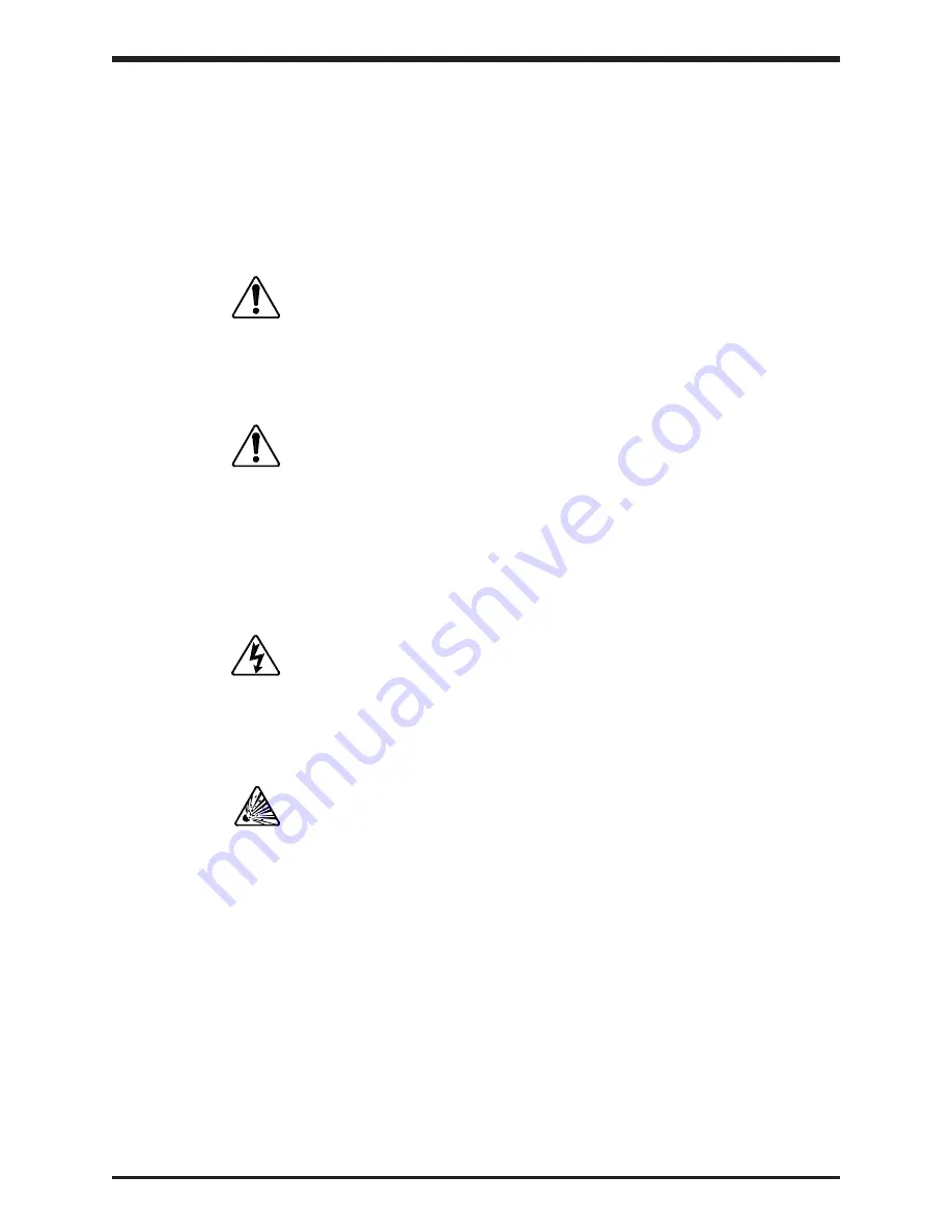
Safety Symbols appear in this manual in the following ways:

1)

Danger symbol - The danger symbol is an exclamation mark enclosed in a triangle which
precedes the 3/16" high letters spelling the word "DANGER". The Danger symbol
indicates an imminently hazardous situation which, if not avoided, will result in death or
serious injury. This signal word is to be limited to the most extreme situations:

2)

Caution symbol - The caution symbol is an exclamation mark enclosed in a triangle which
precedes the 3/16" high letters spelling the word "CAUTION". The Caution symbol
indicates a potentially hazardous situation which, if not avoided, may result in minor or
moderate injury. It may also be used to alert against unsafe practices:

Other 

warning symbols may appear along with the Danger and Caution symbol and are used to indicate

a potentially hazardous situation which, if not avoided, could result in death or serious injury:

1)

Electrical warnings - The electrical warning symbol is a lighting bolt mark enclosed in
a triangle. The Electrical warning symbol is used to indicate high voltage locations and
conditions that may cause serious injury or death if the proper precautions are not
observed:

iii

DANGER

CAUTION

2)

Explosion warnings - The explosion warning symbol is an explosion mark enclosed in
a triangle. The Explosion warning symbol is used to indicate locations and conditions
where molten, exploding parts may cause serious injury or death if the proper
precautions are not observed:

For the purpose of this manual and product labels, a 

Qualified Person is one who is familiar with the

installation, construction, operation and maintenance of the equipment and the hazards involved. In
addition, this person must:

1)

Carefully read the entire operation manual.

2)

Be trained and authorized to safely energize, de-energize, clear faults, ground, lockout
and tag circuits and equipment in accordance with established safety practices.

3)

Be trained in the proper care and use of protective equipment such as safety shoes,
rubber gloves, hard hat, safety glasses, face shields, flash clothing, and etc. in
accordance with established safety practices.

4)

Be trained in rendering first aid.

efesotomasyon.com -Toshiba inverter,drive,servo,plc

Summary of Contents for TOSVERT-130P2

Page 1: ...October 1996 Part 39824 002 DIGITAL TRANSISTOR INVERTER TOSVERT 130P2 6 PULSE INPUT and 12 PULSE INPUT OPERATION MANUAL efesotomasyon com Toshiba inverter drive servo plc ...

Page 2: ...vision and any statements contained herein do not create new warranties or modify the existing warranty Any electrical or mechanical modification to this equipment without prior written consent of Toshiba International Corporation will void all warranties and may void UL listing Unauthorized modifications may cause equipment malfunction and or failure that could result in possible death or serious...

Page 3: ...uipment performance and longevity The manual is divided into major sections of interest All of the initial inspection storage installation and operating precautions can be found in Sections 1 and 2 with Section 3 and 4 containing all of the standard specifications and information on grounding wiring and cable sizes Section 5 contains information about the printed circuit board layouts connectors w...

Page 4: ...k enclosed in a triangle The Electrical warning symbol is used to indicate high voltage locations and conditions that may cause serious injury or death if the proper precautions are not observed iii DANGER CAUTION 2 Explosion warnings The explosion warning symbol is an explosion mark enclosed in a triangle The Explosion warning symbol is used to indicate locations and conditions where molten explo...

Page 5: ...1 3 2 P2 Configuration 3 1 3 3 Standard Specifications 3 2 4 0 Wiring 4 1 4 1 Selection of Main Circuit Wiring Equipment and Standard Cable Sizes 4 1 4 2 Grounding 4 2 4 3 Simple Connection Diagram for 6 Pulse Drive 4 3 4 4 Simple Connection Diagram for 12 Pulse Drive 4 6 5 0 PWB Layout Jumpers and Terminal Connections 5 1 5 1 Control Board for P2 4600 through P2 470KB 5 1 5 2 Driver Board for P2 ...

Page 6: ... 9 1 Setup Parameters 9 1 9 2 User Group Parameters 9 3 9 3 Communication Group Parameters 9 5 9 4 Jump Frequency Group Parameters 9 7 9 5 Display Group Parameters 9 8 9 6 Speed Group Parameters 9 9 9 7 Pattern Frequency Group Parameters 9 10 10 0 Input Terminal Operating Functions 10 1 10 1 Input Terminal Selection Function 10 1 10 2 Starting Stopping Remote Control 10 2 10 3 Remote Control Frequ...

Page 7: ...ife 12 2 13 0 Dimensions Weights Handling 13 1 13 1 Cubicle Dimensions for 60 200 HP Units 13 1 13 2 Cubicle Dimensions for 250 300 HP Units 13 2 13 3 Cubicle Dimensions for 400 HP Unit 13 3 13 4 Cubicle Dimensions for 500 700 HP Units 13 4 13 5 Unit Weights 13 5 13 6 Handling 13 6 efesotomasyon com Toshiba inverter drive servo plc ...

Page 8: ...r specified on the nameplate conform to the order specifications 1 2 Storage 1 Store in a well ventilated location and preferably in the in the original carton if the inverter will not be used immediately after purchase 2 Avoid storage in locations with extreme temperatures high humidity dust or metal particles 1 3 Disposal Please contact your state environmental agency for details on disposal of ...

Page 9: ...ould be run inside the conduit with the input output and control power cables The metal of the conduit is not an acceptable ground 9 Connect three phase power of the correct voltage to input terminals L1 L2 L3 R S T of standard 6 pulse units or connect to the input of phase shifting transformer in 12 pulse units 10 Connect three phase power from output terminals T1 T2 T3 U V W to a motor of the co...

Page 10: ...ect the inverter from the motor before applying a test or bypass voltage to the motor 7 Do not operate this unit with the cabinet door open 8 Use caution when setting output frequency Overspeeding of the motor can cause serious damage to the motor and or the driven load equipment 9 Use caution when setting the acceleration and or deceleration time Unnecessarily short acc dec time can cause undue s...

Page 11: ...rect operation of the equipment for reasons of reliable and safe performance It is important to make arrangements for such a check and that time is allowed for it When power is applied for the first time the inverter will come up in the factory settings See section 7 2 If these settings are incorrect for the application trial run then the correct settings should be programmed from the control pane...

Page 12: ... 3 0 Specifications 3 1 Power Ratings RATINGS These units are UL CUL Underwriters Laboratories Inc listed 3 2 P2 Configuration Use the following configuration chart for options selecting AC input fusing and DC links Inverter Input Fuse DCL P2 4600 Option No P2 4750 Option No P2 410HP Option No P2 412HP Option Available P2 415HP Option Available P2 420HP Standard Available P2 425HP Standard Availab...

Page 13: ...n braking Start up frequency adjustment 0 to 10 Hz braking voltage adjustment 0 to 20 braking time adjustment 0 to 5 seconds Forward or reverse run Forward run when F CC closed reverse run when R CC closed reverse run when both F CC and R CC closed coasting stop when ST CC open emergency coast stop by a command from operating panel Jogging run Jogging run engaged when N O contact is closed adjustm...

Page 14: ...uit capacitors charge indicator located inside enclosure indicator Output signals Fault detection signal One form C contact 250 Vac 30 Vdc 2 Amp Low speed reach signals Open collector output 24 Vdc 50 mA maximum Upper limit lower limit Open collector output 24 Vdc 50 mA maximum frequency signals Frequency meter output Ammeter rated at 1mAdc at full scale or voltmeter rated at and ammeter output 7 ...

Page 15: ...al Control Equipment Table 24 The selection of breakers for this table is in accordance with 1990 NEC Article 430 The selection of these breakers takes into consideration motor starting at the low end of the output voltage specifications but does not consider the use of high efficiency motors For multiple motor applications the magnetic only MCP should be replaced by a thermal magnetic MCCB The MC...

Page 16: ...l or Canadian Electrical Codes may require external motor overload protection 3 When wiring with parallel conductors the conductors should be kept together in phase sets with U1 V1 W1 in one conduit and parallel conductors U2 V2 W2 in another conduit The ground conductor should be in one of these conduits 4 2 Grounding The inverter should be grounded in accordance with Article 250 of the National ...

Page 17: ...ctions see Page 5 5 through 5 6 4 Contact Toshiba when interfacing with a process controller POWER SUPPLY IV PP CC RR AD2 SS3 JOG SS2 SS1 CC RST F R ST RJ R38 R40 44 R41 46 L3 T L2 S L1 R LOW LL RCH UL FM AM CC P24 FLC FLB FLA FAULT FAULT SIGNAL OUTPUT OV OH T3 W T2 V T1 U MCCB GND E 0 5 VDC 4 20 mA AUTO REFERENCE DIGITAL OPERATION PANEL P2 INVERTER INPUT POWER SELECTION 415 460V 50 60 Hz 400 440V...

Page 18: ...s and functions see Page 5 5 through 5 6 4 Contact Toshiba when interfacing with a process controller IV PP CC RR AD2 SS3 JOG SS2 SS1 CC R ST RJ R38 R40 R46 L1 R LOW LL RCH UL FM AM CC P24 FLC FLB FLA FAULT FAULT SIGNAL OUTPUT OV OH T3 W T2 V T1 U MCCB GND E 0 5 VDC 4 20 mA AUTO REFERENCE DIGITAL OPERATION PANEL P2 INVERTER POWER SUPPLY 460V 60 Hz 380V 50 Hz 415V 50 Hz F RST L2 S L3 T INPUT POWER ...

Page 19: ...s see Page 4 1 3 For terminal connections and functions see Page 5 5 through 5 6 4 Contact Toshiba when interfacing with a process controller IV PP CC RR AD2 SS3 JOG SS2 SS1 CC R ST L1 R LOW LL RCH UL FM AM CC P24 FLC FLB FLA FAULT FAULT SIGNAL OUTPUT OV OH T3 W T2 V T1 U MCCB GND E 0 5 VDC 4 20 mA AUTO REFERENCE DIGITAL OPERATION PANEL P2 INVERTER F RST L2 S L3 T POWER SUPPLY efesotomasyon com To...

Page 20: ... shift phase 30 IV CC RR PP JOG SS2 SS1 CC AD2 SS3 ST R F RST RJ R38 R41 46 R40 44 R1 T1 S1 R2 T2 S2 MCCB1 MCCB2 AUTO RUN SIGNAL FAULT SIGNAL OUTPUT FM AM CC P24 LOW LL RCH UL GND E 0 5 VDC 4 20 mA AUTO REFERENCE FLC FLB FLA OV OH T1 U T3 W T2 V 415 460V 50 60 Hz 400 440V 50 60 Hz FAULT 3 Ø 460V 60Hz INCOMING POWER TOSVERT 130 P2 STANDARD CONNECTION MODEL 4600 TO 420HP 460 240 240 PHASE SHIFTING T...

Page 21: ...wye outputs which shift phase 30 IV CC RR PP JOG SS2 SS1 CC AD2 SS3 ST R F RST RJ R38 R46 R40 R1 T1 S1 R2 T2 S2 MCCB1 MCCB2 AUTO RUN SIGNAL FAULT SIGNAL OUTPUT FM AM CC P24 LOW LL RCH UL GND E 0 5 VDC 4 20 mA AUTO REFERENCE FLC FLB FLA OV OH T1 U T3 W T2 V 460V 60 Hz 415V 50 Hz FAULT 3 Ø 460V 60Hz INCOMING POWER TOSVERT 130 P2 STANDARD CONNECTION MODEL 430HP 460 240 240 PHASE SHIFTING TRANSFORMER ...

Page 22: ... 460V input and two 240V delta wye outputs which shift phase 30 IV CC RR PP JOG SS2 SS1 CC AD2 SS3 ST R F RST R1 T1 S1 R2 T2 S2 MCCB1 MCCB2 AUTO RUN SIGNAL FAULT SIGNAL OUTPUT FM AM CC P24 LOW LL RCH UL GND E 0 5 VDC 4 20 mA AUTO REFERENCE FLC FLB FLA OV OH T1 U T3 W T2 V FAULT 3 Ø 460V 60Hz INCOMING POWER TOSVERT 130 P2 STANDARD CONNECTION MODEL 440HP TO 470KB 460 240 240 PHASE SHIFTING TRANSFORM...

Page 23: ...1200 5 1 CN20 CN3 CN2 CN11 See Detail 1 Page 5 3 JP1 JP2 CN10 FL RY CN7 See Terminal Block Detail Page 5 3 CN8 CN1 CN4 CN5 CN6 CN4B CN4A CN4C CP4 CP1 CP2 CP5 CP3 CN12 Note 1 CP1 CP2 CP3 CP4 and CP5 are service testpoints 2 Do not adjust JP4 3 Charge LED indicates charged capacitors DO NOT TOUCH internal parts if lighted Charge LED JP4 Do Not Adjust efesotomasyon com Toshiba inverter drive servo pl...

Page 24: ...o Not Adjust Do Not Adjust CN1A Power LED 1 Note 1 Potentiometer 21RH OP is the main circuit overvoltage detection trip set This adjustment is factory set and any ADJUSTMENT BY THE USER SHOULD NOT BE ATTEMPTED 2 Potentiometer 22RH MUV is the main circuit undervoltage detection trip set This adjustment is factory set and any ADJUSTMENT BY THE USER SHOULD NOT BE ATTEMPTED 3 Do not adjust J4 and J21 ...

Page 25: ...rd Terminal Block Details The control driver board terminal block is shown in detail below Each of the twenty one terminals is functionally labeled See Pages 5 5 and 5 6 for a list of terminal functions CC RST AD2 JOG SS2 SS3 FM FLA P24 FLC FLB PP AM LOW RCH UL LL RR IV CC ST F R CC SSI Control Board Terminal Block Detail Reference pages 5 1 JP2 JP1 I V 10V 5V Detail 1 Reference page 5 1 efesotoma...

Page 26: ...terminal input should be set to 1 on See page 7 5 Use when inputting 0 5Vdc external reference signal to terminal IV P Prg parameter 2 priority of RR terminal input should be set to 0 on See page 7 5 Use when inputting a 4 0 20mA external reference signal to terminal IV P PrG parameter 2 priority of RR terminal input should be set to 0 on See page 7 5 Use when not inputting any external reference ...

Page 27: ...r limit is reached The choice is determined by settings of the Output Terminal Selection function 0 tb See page 9 1 FM Output terminal for an external analog frequency meter Use either an ammeter rated at 1mAdc at full scale or a voltmeter rated at 7 5Vdc at full scale scaled for frequency AM Output terminal for an external analog ammeter Use either an ammeter rated at 1mAdc at full scale or a vol...

Page 28: ...S3 Input terminal for multispeed run frequencies Depends on setting of function 1 tb SS1 JOG SS2 terminals See Page 10 1 RST With RST CC shorted the inverter s protective function resets CC This is the common return for ST F R SS1 JOG SS2 AD2 SS3 one of three and RST terminals Do not connect to GND E GND E The inverter earth ground terminal three provided Do not connect to common return terminal C...

Page 29: ...o auto mode first press off key otherwise inverter must be at 0 Hz If auto key is pressed while still running in manual mode an Err 7 will flash See page 8 2 6 0 Operating Panel 6 1 Operating Panel Layout The operating panel allows the user to enable or disable the keypad input commands from the keypad and monitor the inverter operation on the LED displays The panel consists of the keypad and LED ...

Page 30: ...thin the group or setup parameters write data changes into the non volatile memory System status information is available while drive is running Key used to scroll through the parameter groups and returns to frequency setting if in any other mode When data changes have been made in error this key will allow user to clear data back to data 0 if allowed Also resets trips or returns to frequency mode...

Page 31: ...ontact Toshiba for information Both LED s are normally OFF when the monitor is displaying operating 4 Monitor display frequency or scaled operating frequency from the display scaler 5 LED 5 is ON and LED 4 is OFF when unit is in a patterned run sequence Both LED s are ON when the unit is in the parameter setting mode using the operating panel keypad and the motor is not running Both LED s are FLAS...

Page 32: ...refore some characters of the alphabet will appear as special symbols and others are not used at all The tables below show the numbers and characters that are used and how each appears on the 7 segment display 6 4 Numerics 0 1 2 3 4 5 6 7 8 9 LED display Characters A b C d E F G H I J L M n O P r S t U v y LED display or efesotomasyon com Toshiba inverter drive servo plc ...

Page 33: ...ERS This parameter group is accessible from the group parameter menu The menu can be scrolled by repeated pressing of the PRG key This group contains features for setting three different operating patterns jump frequency and jump width This group also contains selections for PID control and adjustments DISPLAY GROUP PARAMETERS This parameter group is accessible from the group parameter menu The me...

Page 34: ...ff 0 9 3 1 On 3 Torque boost 0 30 3 1 9 3 4 Base frequency of maximum voltage level 30 120 Hz 60 Hz 9 3 5 Standard setting mode selection 0 Factory settings 0 9 3 1 50 Hz motor 2 60 Hz motor 3 Reset to factory settings 6 Acceleration time 2 3 0 1200 sec 10 0 sec 9 3 7 Deceleration time 2 3 0 1200 sec 10 0 sec 9 3 8 Pattern of ACC DEC 1 0 Linear 0 9 3 1 S curve 2 C curve 9 Pattern of ACC DEC 2 0 Li...

Page 35: ...12 bit binary relativity input 3 3 number BCD input 4 3 number BCD input 5 Pulse frequency reference inout 6 Multi speed input 7 Selection 1 with write signal 8 Selection 2 with write signal 9 Selection 3 with write signal 10 Selection 4 with write signal 11 Selection 5 with write signal 12 Selection 6 with write signal 8 Inverter number 0 31 0 9 6 9 Baud rate RS232 RS485 0 150 1200 0 9 6 1 300 24...

Page 36: ...tion voltage start frequency 0 0 Hz 10 0 Hz 0 0 Hz 9 8 7 DC injection voltage 0 20 0 9 8 8 DC injection time 0 0 5 0 sec 0 0 sec 9 8 9 Output voltage regulation 0 100 100 9 8 10 Overvoltage stall protection select 0 On 0 9 8 1 Off 1 AC line inverter transfer signal 0 Off 0 9 9 1 On 2 Multispeed run frequency 1 LL UL 0 0 Hz 9 9 3 Multispeed run frequency 2 LL UL 0 0 Hz 9 9 4 Multispeed run frequenc...

Page 37: ...n 2 Acc Dec 2 Rev run 1 Acc Dec 3 Rev run 2 Acc Dec 12 Pattern 4 run time 0 8000 0 9 10 13 Pattern 4 drive characteristics 0 Fwd run 1 Acc Dec 0 9 10 1 Fwd run 2 Acc Dec 2 Rev run 1 Acc Dec 3 Rev run 2 Acc Dec 14 Pattern 5 run time 0 8000 0 9 10 15 Pattern 5 drive characteristics 0 Fwd run 1 Acc Dec 0 9 10 1 Fwd run 2 Acc Dec 2 Rev run 1 Acc Dec 3 Rev run 2 Acc Dec 16 Pattern 6 run time 0 8000 0 9...

Page 38: ...s reached individual parameters within the group can be exhibited by alternately pressing the up or down key Value of exhibited parameter can be read by pressing READ WRITE key Value of exhibited parameter can be changed by continued pressing of up or down key When desired value is reached press the READ WRITE key to store new value When P SEL mode for pattern run is set to 0 pattern run times Pt ...

Page 39: ...g the READ WRITE key after output frequency is displayed Trips or errors that have occurred up to a total of four will be displayed in order immediately after the keypad software version display Key Display Status Condition Inverter is in the off position when OFF is flashing Inverter is ready to run from terminal or computer interface Inverter is ready to run from keypad and manual control LED is...

Page 40: ...tage is low Stall prevention is activated when flashing C appears in front of output frequency Overvoltage limitation is activated when flashing P appears in front of output frequency Overload detection is activated when flashing L appears in front of output frequency This error occurs while trying to switch from manual to automatic mode or automatic mode to manual while inverter is outputting a f...

Page 41: ...ord of each trip up to four is created and can be viewed during the normal status monitoring scroll These recorded trips are viewed immediately after the keypad s software version in the order that they occurred as the READ WRITE key is pressed These trips remain in the memory until replaced by new trips 8 3 Key Display Status Condition Overcurrent occurred during an acceleration Overcurrent occur...

Page 42: ...OFF ON OFF ON OFF ON ON OFF OFF ON ON OFF OFF ON ON ON OFF ON ON ON ON OFF OFF OFF ON OFF OFF OFF ON OFF ON ON ON OFF ON ON ON ON OFF OFF ON ON OFF OFF ON ON OFF ON ON ON OFF ON ON ON ON OFF ON ON ON OFF ON ON ON ON ON ON ON ON ON OFF ON OFF ON OFF ON OFF ON OFF OFF ON ON OFF OFF ON ON Implies a closed contact or short between terminals OFF Implies an open contact or no connection between terminal...

Page 43: ...erminal RCH UL RCH and terminal LOW LL LL A reading such as the example below indicates that terminals RCH and LL are on collector shorted to ground 8 5 Display RCH UL Display LOW LL OFF OFF OFF OFF OFF ON OFF ON ON OFF ON OFF ON ON ON ON RCH Output frequency is within the set reach frequency range or acc dec is complete LOW Output frequency is equal to or greater than low speed frequency UL Outpu...

Page 44: ...Sets the percentage of the input signal on terminal IV which is used to reference the 1 output frequency P1 designated by function F P1 See page 10 7 POINT 1 OUTPUT FREQUENCY ITEM 6 Sets the output frequency used for reference point function FP 1 See page 10 7 TERMINAL IV REFERENCE POINT 2 ITEM 7 Sets the percentage of the input signal on terminal IV which is used to reference the 2 output frequen...

Page 45: ...r or Vf motor with or without soft stall as shown in the following overload detection curves 9 2 100 60 40 40 0 45Hz 0 Fmax Fmax 100 60 OVERLOAD DETECTION LEVEL OVERLOAD DETECTION LEVEL FREQUENCY FREQUENCY Curve for standard motors Curve for Vf motors efesotomasyon com Toshiba inverter drive servo plc ...

Page 46: ...ate time required to accelerate from 0Hz to the maximum frequency FH Use function SEL2 to select either acceleration time 1 or 2 Setting this time too low can cause undue stress and over current tripping of the drive DECELERATION TIME 2 ITEM 7 Sets the time required to decelerate from maximum safe frequency FH to 0Hz Use function SEL2 to select either deceleration time 1 or 2 Setting this time too...

Page 47: ...ifugal pumps are the most common types of loads associated with the variable torque load V f pattern Factory default setting is variable torque TIMED STOP COAST TO STOP SELECTION ITEM 12 Use this function to select either a timed deceleration to a stop or a power off coast to a stop PERSONAL LOCK OUT CODE ITEM 13 Use this function to establish a security entry code for programming the inverter fun...

Page 48: ...is selected the inverter will automatically try to reset itself and restart the motor when a protective function activates fault trip The following chart shows the auto reset procedure for over current and over voltage fault trips If the inverter is able to reach the original operating speed where the trip occurred while trying to restart then the reset process counter resets to zero The process n...

Page 49: ... configurations that can be assigned to these terminals OPTION CARD MULTI FUNCTIONAL SELECTIONS ITEM 7 Use this function to select various configurations for the optional Multi function Printed Circuit Board This is used only when the Multi Functional Option Board is installed INVERTER NUMBER ITEM 8 Use this function to select a number between 0 and 31 to assign the inverter This will electronical...

Page 50: ...IDTH 2 ITEM 4 Use this function to set the bandwidth for Jump Frequency 2 JUMP FREQUENCY 3 ITEM 5 Use this function to set the beginning point of a third frequency bandwidth to be skipped when running a motor This function is to be used in conjunction with the bandwidth which is set by Jump Width 3 This function should be used when a third resonant frequency should be avoided JUMP WIDTH 3 ITEM 6 U...

Page 51: ...M 5 Use this function to set the speed reach detection frequency in the center of the speed reach detection range See functions Speed Reach Selection and Speed Reach Detection Range DC INJECTION VOLTAGE START FREQUENCY ITEM 6 Use this function to set the frequency at which DC injection voltage will begin to be applied to a motor during a decelerating stop This function is used for precise position...

Page 52: ...rd of 7 preset speed frequencies SR3 This frequency is run by input terminal connections See Input Terminal Operations Page 10 1 MULTISPEED RUN FREQUENCY 4 ITEM 5 Use this function to set up 4th of 7 preset speed frequencies SR4 This frequency is run by input terminal connections See Input Terminal Operations Page 10 1 MULTISPEED RUN FREQUENCY 5 ITEM 6 Use this function to set up 5th of 7 preset s...

Page 53: ...ion to set the run time of the preset speed frequency SR2 PATTERN 2 DRIVE CHARACTERISTIC ITEM 9 Use this function to select the type of run for preset speed frequency 2 The selection can be a forward or reverse run using either ACC DEC 1 or ACC DEC 2 PATTERN 3 RUN TIME ITEM 10 Use this function to set the run time of the preset speed frequency SR3 PATTERN 3 DRIVE CHARACTERISTIC ITEM 11 Use this fu...

Page 54: ...or moving in small increments when precise positioning of motor driven equipment is required JOG STOP SELECT ITEM 21 Use this function to select between three methods of stopping during a jog run START UP FREQUENCY ITEM 22 Use this function to set the frequency at which the inverter will begin operating In the manual control mode the frequency display will change as the up and down keys are presse...

Page 55: ...es the Frun Fhys point the drive will ramp the motor to that speed The inverter will continue to follow the reference signal until it falls below the Frun Fhys at which time the drive will ramp the motor to a stop See the illustration below 9 12 100 FH Stop Start Frun Fhys Frun Frun Fhys OUTPUT FREQUENCY FREQUENCY REFERENCE SIGNAL 0 efesotomasyon com Toshiba inverter drive servo plc ...

Page 56: ...tch between the ACC DEC patterns 1 and 2 provided SEL2 0 If SEL2 1 then the only pattern available is given by ACC2 DEC2 or Pt 2 With AD2 CC terminals shorted ON all ACC DEC patterns are run using the settings of the ACC2 DEC2 or Pt 2 parameters Input terminal Terminal Connection Selected operating selection AD2 SS3 CC JOG SS2 CC SS1 CC frequency parameter 1 tb OFF OFF OFF Operating frequency set ...

Page 57: ...ion and Deceleration rates are determined by the preset values of function ACC1 ACC2 and DEC1 DEC2 4 When switching from a forward run to a reverse run the motor will decelerate to a stop then accelerate in the reverse direction 10 3 Remote control Frequency Setting The drive can be run at various frequencies by use of external analog voltage and current control signals applied to terminals IV and...

Page 58: ...celerate at the selected rate during deceleration stop coast to stop and DC injection stop 3 F CC must be broken for DC injection to be applied breaking only JOG SS2 CC allows the inverter to accept other input signals and is not a true off 4 See table on next page for terminal inputs and actions 10 5 Resetting After a Trip Pressing reset on the keypad resets the inverter faults Momentarily closin...

Page 59: ...racteristics including the run direction to be used is located in Pattern Frequency Group Parameters P PrG Item 7 9 11 13 15 17 and 19 The run time set for each pattern includes the ACC DEC time required to reach that particular run frequency Therefore care must be taken when choosing run times For example if the pattern run time is set for 30 seconds and the acceleration time required to reach th...

Page 60: ...ove power and place the jumper connections JP1 and JP2 in the correct positions for the type of feedback signal used power can then be applied again See reference signal terminal connections and functions on page 5 4 and 5 5 2 Set acceleration and deceleration times to 5 seconds see Setup Parameters Item 1 and 2 3 Adjust the bias and gain for the systems feedback signal For example typically the m...

Page 61: ...are things which will cause the PID loop to operate incorrectly 1 FEEDBACK Make sure that the feedback signal has the correct polarity Make sure that jumpers JP1 and JP2 are correctly set See detail 1 on page 5 3 2 SOFTWARE Make sure that the inverter main software is Version 5 3 see page 8 1 Normal Status Monitoring 3 SETPOINT Make sure that the setpoint potentiometer is connected correctly 4 STA...

Page 62: ...1 40 In the above graph the inverter has an output frequency of 20Hz even with a 0 input signal Also notice that the maximum output frequency is never reached unless the input signal goes above 100 i e a 7Vdc input signal is considered a 140 input signal when using a 0 5Vdc input FH 20 33 0 P2 100 P1 66 In the above graph the inverter has a negative output In other words as the input signal increa...

Page 63: ...e LOW Outputs a signal when frequency is greater than or equal to the LOW SPEED DETECTION VALUE LF RCH Outputs a signal based upon the selection of the RCH parameters rCH rrCH FrCH All output signals are open collector with 50mAdc 24Vdc ratings The illustrations below show output timing diagrams for the upper and lower frequency limits and for low speed and speed reach signals 11 1 LL ON ON Upper ...

Page 64: ...ote When an output frequency fluctuates in the vicinity of a frequency to be reached the reach signal may alternately turn on and off because of the lack of hysteresis in the reach signal 11 3 Fault Detection Output Terminals When any of the inverter s system protection features are activated and the inverter trips See list of probable causes on Page 8 3 the cause of the problem will be displayed ...

Page 65: ...ncy Meter FM 11 3 Terminal Connection FM CC FM Frequency Meter Zero adjust screw Note Use a 1mAdc ammeter or 7 5Vdc voltmeter Connect the meter across terminals FM CC Use shielded cable 1000 ft maximum length Use the following procedure to calibrate the FM meter 1 Start the inverter to output a run frequency such as 60 Hz 2 Press down key while pressing CLEAR RESET key to display 3 Press the RUN k...

Page 66: ... to calibrate the AM meter 1 Start the inverter to output a run frequency such as 60 Hz 2 Press down key while pressing CLEAR RESET to display 3 Press either the up or down key to display 4 Press the RUN key to display 5 Adjust the analog meter reading to match the digital display reading by pressing the up or down keys 6 Press the READ WRITE key to store this setting to non volatile EEPROM memory...

Page 67: ...ations in micrometers Presence of corrosive gas Availability of air conditioning Number of phases Voltage between L1 phase and L2 phase Power Voltage between L2 phase and L3 phase source Voltage between L3 phase and L1 phase Number of Hz Problem occurredhours after motor had been started Motor has been stopped for hours Phenome State of Problem occurred during periodic inspection non motor when Pr...

Page 68: ...ms Use the following service life chart as a guide for major part periodic replacement when the equipment is used in a standard installation service environment Service Life Replacement Chart Part Name Service Life Remarks Large capacity 5 Years To be electrified semiannually in electrolytic capacitor case of long term disuse Cooling Fan 3 Years Contact relays 500 000 operations Connectors 100 ope...

Page 69: ...eights Handling 13 1 Cubicle Dimensions for 60 200 HP 6 Pulse Units PLEASE NOTE Cubical dimensions shown are for standard 6 pulse units only Contact Toshiba for 12 pulse dimensions efesotomasyon com Toshiba inverter drive servo plc ...

Page 70: ...3 2 Cubicle Dimensions for 250 300 HP 6 Pulse Units PLEASE NOTE Cubical dimensions shown are for standard 6 pulse units only Contact Toshiba for 12 pulse dimensions efesotomasyon com Toshiba inverter drive servo plc ...

Page 71: ...3 PLEASE NOTE Cubical dimensions shown are for standard 6 pulse units only Contact Toshiba for 12 pulse dimensions 13 3 Cubicle Dimensions for 400 HP 6 Pulse Unit efesotomasyon com Toshiba inverter drive servo plc ...

Page 72: ...LEASE NOTE Cubical dimensions shown are for standard 6 pulse units only Contact Toshiba for 12 pulse dimensions 13 4 Cubicle Dimensions for 500 700 HP 6 Pulse Units efesotomasyon com Toshiba inverter drive servo plc ...

Page 73: ...0 345 P2 412HP 775 352 P2 415HP 775 352 P2 420HP 865 393 P2 425HP 935 425 P2 430HP 1125 510 P2 440KB 1200 544 P2 450KB 1600 725 P2 460KB 1600 725 P2 470KB 1600 725 13 5 Unit Weights 13 5 Approximate weight of build up assembly including inverter efesotomasyon com Toshiba inverter drive servo plc ...

Page 74: ...right position only b Select rigging lengths to compensate for any unequal weight distribution c Do not exceed the 45 maximum between the vertical and lifting cables d Use only slings with safety hooks or shackles Do not pass ropes or cables through the holes in the lifting angle 5 Use extreme caution when moving sections with rods or pipe rollers There is a tendency for the control center to tilt...

Page 75: ...A INTERNATIONAL CORPORATION INDUSTRIAL DIVISION 13131 West Little York Rd Houston Texas 77041 Tel 713 466 0277 Fax 713 466 8773 Telex 762078 Printed in U S A efesotomasyon com Toshiba inverter drive servo plc ...

Reviews: