background image

– 8 –

EN

ES

ES

ES

ES

ES

ES

ES

ES

ES

ES

ES

ES

ES

ES

ES

ES

ES

ES

ES

ES

ES

ES

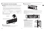
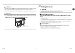
CAUTION

Please follow the wire as shown above to avoid condensation water flowing down the wire to the electronic components.

When routing wires, ensure that the connecting wires shall not be clamped by objects like the terminal block.

If the indoor unit is installed outside the wall or ceiling, the exposed wires must be covered with insulation sleeves with a 
thickness of more than 1 mm.

WARNING

Do not route the connecting  wire of the 3DW Diffusor together with the power cable of the indoor unit. Otherwise, it may 
result in abnormal operation.

3DW Diffusor

Do not route the connecting wire together with the power cable

Power cable of the indoor unit

11

Setting Parameter

CAUTION

Be sure to set parameters before use.

If the machine is running without setting parameters, it cannot be operated normally.

Setting external static pressure

Please refer to the installation manual of indoor unit for the setting method of external static 
pressure.

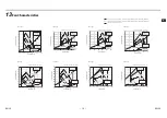
The pressure loss characteristics of 3DW Diffusor will affect the external static pressure. Please refer to the attached fan 
characteristics for details.

To avoid deviation from the operating range, please adjust the air volume by adjusting the air doors set at the suction and 
air outlets under the premise that the maximum air volume position (horizontal louver: fully open; vertical louver: front) 
that the louvers can provide is the standard air volume.

* If the wind direction is changed under the condition of non-standard air volume, the system may start the protection 

program for upper and lower air volume limit, resulting in failure of operation.

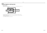
Setting 3DW Diffusor

For the setting method of 3D louver, please refer to the manual of the remote controller.

Remote controller: RBC-ASCU21-C (via APP) or RBC-ASCU11-C 

Setting content: the item code is [019], [119], and the parameter is [0002].

* If the above parameters are not set, the louvers will not be operated normally.

EN-15

EN-16

Summary of Contents for TCB-TDL0141SDY-E

Page 1: ...s Ελληνικα Svenska Suomi Norsk Dansk Română Български Eesti Latviski Slovenčina Slovenščina AIR CONDITIONER ACCESSORY Installation Manual 3DW Diffusor Model name TCB TDL0141SDY E TCB TDL0181SDY E TCB TDL0271SDY E TCB TDL0141SDY TR TCB TDL0181SDY TR TCB TDL0271SDY TR For commercial use Ticari kullanım için ...

Page 2: ...ctions may result in drop noise vibration water leakage and other problems Only a qualified installer or qualified service person is allowed to carry out the installation work Improper installation may result in water leakage electric shock fire and other problems Before the installation maintenance repair or removal work please set the circuit breaker to the OFF position otherwise there is a risk...

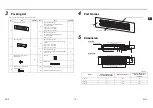
Page 3: ...ulation sponge Inside heat insulation for mounting frame 190 33 6 1 3 Fixing screw for mounting frame M4x8 16 9 Wire clip 1 10 Binding belt 2 4 Fixing screw for front panel assembly M4x25 6 11 Owner s manual 1 12 Installation manual this manual 1 4 Part Names 5 Dimension Unit mm Horizontal louver swing up and down Vertical louver swing left and right Panel 34 5 11 80 5 7 5 21 6 61 180 94 42 Distan...

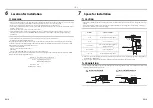
Page 4: ...door 3 Kitchen 4 A place where the 3DW Diffusor is exposed to the outdoor air directly In the above places please paste heat insulation materials such as sponges on the panel and the horizontal louver of 3DW Diffusor that are exposed to high humidity air Reference Test conditions for condensation Indoor Dry ball temperature 27 C Wet ball temperature 24 C Air volume Low Running time 4 hours 7 Space...

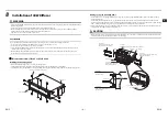
Page 5: ... frame Only 12 places on TCB TDL0141SDY C need to be fixed meaning there will be 4 fixing screws for mounting frame 3 left 3 Fixing screw for mounting frame 2 Mounting frame Indoor unit Sticking sponge on mounting frame Please stick 2 pieces of sponge 5 and 2 pieces of sponge 6 that are attached with the machine to the fixed screws for mounting frame 3 Please stick the attached sponge 7 onto the a...

Page 6: ...g and fix the mounting frame with screws Please install the indoor unit and connect the pipelines Perform the heat insulation treatment on the refrigerant connecting pipe and drainage pipe For details refer to the installation manual of the indoor unit Please make the drill on the wall according to Drilling on the wall Please refer to the figure below to install the wooden frame locally purchased ...

Page 7: ...cting wire of the front panel assembly 1 to the wall opening and then push the front panel assembly 1 into the opening Temporarily fix two screws at the central part of the panel assembly 1 with the complimentary fixing screws for panel assembly M4x25 4 Similarly after temporarily fixing the remaining 4 screws tighten all the screws 6 in total Pay attention to the tightening sequence of the screws...

Page 8: ... drainpipe Side cover of PCB board Plug of PCB board Plug the connector of the wire into the PCB board socket CN510 white To protect the PCB board from the external pressure fix the connecting wire on a wire clip on the back of the side cover of the PCB board about 100 mm away from the plug with the binding belt 10 Close the side cover of the PCB board and fix it with 2 screws Tidy wires Tidy the ...

Page 9: ...l static pressure Please refer to the installation manual of indoor unit for the setting method of external static pressure The pressure loss characteristics of 3DW Diffusor will affect the external static pressure Please refer to the attached fan characteristics for details To avoid deviation from the operating range please adjust the air volume by adjusting the air doors set at the suction and a...

Page 10: ...door unit before the trial operation of the 3DW Diffusor For details refer to the installation manual of the indoor unit Please control the operation of the horizontal louver and vertical louver by the remote controller and confirm that the movement and sound are normal Refer to the manual of the remote controller for operation The clearance on the right side of the horizontal louver must be even ...

Page 11: ...35 200 300 400 500 600 700 Static Pressure Pa Blowing downward Blowing horizontally Low 20 Pa Low 10 Pa High 20 Pa High 10 Pa 0 5 10 15 20 25 30 35 40 400 500 600 700 800 900 1000 Static Pressure Pa Blowing downward Blowing horizontally Low 20 Pa Low 10 Pa High 20 Pa High 10 Pa 0 5 10 15 20 25 30 35 40 400 500 600 700 800 900 1000 Static Pressure Pa Blowing downward Blowing horizontally Low 20 Pa ...

Page 12: ...D0X7203601 00 ...
Reviews: