5
6 Spacer (A)
1:1 Model
Connection Interface board box
(Attached to the TCB
́
PX30MUE)
1 P.C. board
Bell mouth
Cut-off part
Bell mouth
Cut-off part
Fixing plate
for terminal block
Upside
Direction of
nameplate
10 Terminal
nameplate
8 Screw to fix
terminal block
2 Terminal block
(U3/U4)
Fixing plate
for terminal block
Upside
Direction of
nameplate
10 Terminal
nameplate
8 Screw to fix
terminal
block
2 Terminal block
(U3/U4)
No.
1
2
3
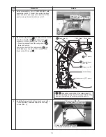
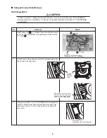
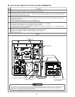
Cut off a part of the bell mouth, which is enclosed with dotted
line shown in the right figure.
Mount terminal block (U3, U4)
2
at the fixing plate position
for terminal block as shown in the right figure of the electric
parts box, with terminal block fixing screws (M4 × 14 )
8
.
Stick the attached terminal nameplate
10
at near the terminal
block along direction shown in the right figure.
Details
Installation Procedure
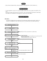
• For installation of “1 : 1 Model” Connection Interface board and removal of relay wire, be sure to wait for a while
(approx. 1 minute) after turning off the power supplies of the air conditioner and the collective control devices.
If not doing so, “1 : 1 Model” Connection Interface board may be damaged.
4-Way Cassette Type
CAUTION
In case to install 1:1 Model Connection Interface, be sure to purchase also “TCB-PX30MUE”
sold separately. For installation, 1:1 Model Connection Interface board box of “TCB-PX30MUE”
is necessary.
RAV-SM
∗∗
∗∗
∗∗
∗∗
∗∗
4UT
∗∗∗∗∗
Procedure
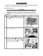
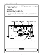
Attach spacer (A)
6
to 1:1Model Connection Interface board
box of the “TCB-PX30MUE” sold separately, and then install
P.C. board
1
.

