6
No
4
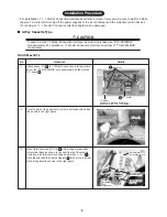
Procedure
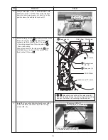
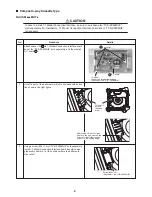
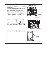
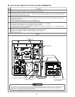
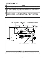
Using a screw (M4 × 14) of “TCB-PX30MUE” sold
separately, install 1:1 Model Connection Interface
board box which was prepared in item No.1 at the
position where the bell-mouth was cut off.
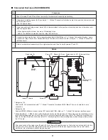
Indoor control P.C. board
CN50 (White)
2 Terminal block
(U3,
U4)
4 Relay wire (B)
3 Relay wire (A)
CN51 (Red)
CN40 (Blue)
1 P.C. board
Fixing screws (M4
Fixing screws (M4 × 8 )
8 )
(Attached to the TCB-PX30MUE)
(Attached to the TCB-PX30MUE)
Connection Interface board cover
Connection Interface board cover
(Attached to the TCB-PX30MUE)
(Attached to the TCB-PX30MUE)
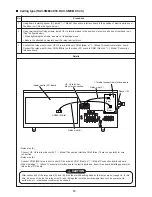
Fixing screws (M4 × 8 )
(Attached to the TCB-PX30MUE)
Connection Interface board cover
(Attached to the TCB-PX30MUE)
Screw (M4
Screw (M4 ×14)
14)
(Attached to the TCB-PX30MUE)
(Attached to the TCB-PX30MUE)
Screw (M4 ×14)
(Attached to the TCB-PX30MUE)
Details
∗
,
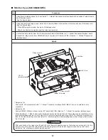
After wiring connection of the relay wires (A)
and (B), fix wirings along the near wirings with banding
band so that there is no catching of wires, and etc.
Install the Connection Interface board cover of the
“TCB-PX30MUE” sold separately with the fixing
screws (M4 × 8).
6
5
Mount the relay wire (A)
to Faston terminal on the
relay terminal (U3, U4)
2
and then connect the
connector to CN40 (Blue) of the P.C. board
1
.
∗
For wiring connection of the relay wire (A)
,
there is no plarity.
Connect connector of the relay wire (B)
from
CN50 (White) on the indoor P.C. board to CN51
(Red) on the P.C. board
1
.

