


2. CIRCUIT SYMBOLS AND SUPPLEMENTARY EXPLANATION
2-1. Precautions for Part Replacement
• In the schematic diagram, parts marked
(ex.
F801) are critical part to meet the safety regulations,
so always use the parts bearing specified part codes
(SN) when replacing them.
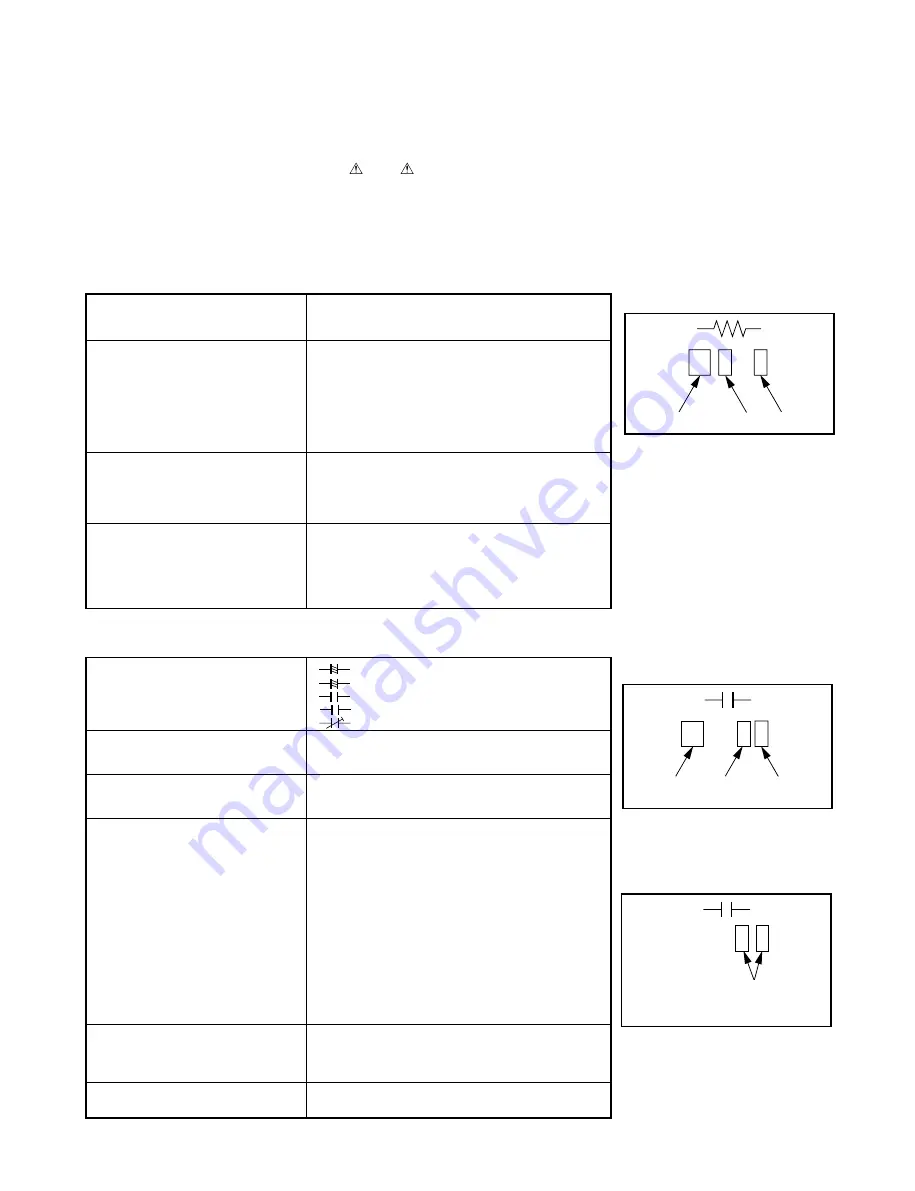
2-2. Solid Resistor Indication
Unit
None
...........
Ω
K
........... k
Ω
M
........... M
Ω
Tolerance
None
........... ±5%
B
........... ±0.1%
C
........... ±0.25%
D
........... ±0.5%
F
........... ±1%
G
........... ±2%
K
........... ±10%
M
........... ±20%
Rated Wattage
(1) Chip Parts
None ......... 1/16W
(2) Other Parts
None ......... 1/6W
Other than above, described in the Circuit Diagram.
Type
None
........... Carbon film
S
........... Solid
R
........... Oxide metal film
M
........... Metal film
W
........... Cement
FR
........... Fusible
Symbol
+
........... Electrolytic, Special electrolytic
NP
........... Non polarity electrolytic
........... Ceramic, plastic
M
........... Film
........... Trimmer
Unit
None
........... F
µ
...........
µ
F
p
........... pF
Rated voltage
None
........... 50V
For other than 50V and electrolytic capacitors,
described in the Circuit Diagram.
Tolerance
(1) Ceramic, plastic, and film capacitors of which
capacitance are more than 10 pF.
None
........... ±5% or more
B
........... ±0.1%
C
........... ±0.25%
D
........... ±0.5%
F
........... ±1%
G
........... ±2%
(2) Ceramic, plastic, and film capacitors of which
capacitance are 10 pF or less.
None
........... more than ±5 pF
B
........... ±0.1 pF
C
........... ±0.25 pF
(3) Electrolytic, Trimmer
Tolerance is not described.
Temperature characteristic
None
........... SL
(Ceramic capacitor)
For others, temperature characteristics are
described. (For capacitors of 0.01
µ
F and
no indications are described as F.)
Static electricity capacity
Sometimes described with abbreviated letters as
(Ceramic capacitor)
shown in Eg. 3.
2-3. Capacitance Indication
100k
Rated Wattage
Type Tolerance
Eg. 1
104
10x10
4
pF (0.1
µ
F)
Temperature characteristic
(or Temperature charact
Static electricity capacity tolerance)
Eg. 3
100m
Temperature
response
Rated
voltage
Tolerance
Eg. 2
Fig. 3-2-1
Fig. 3-2-3
Fig. 3-2-2
• Using the parts other than those specified shall violate
the regulations, and may cause troubles such as
operation failures, fire etc.
Summary of Contents for SD-520EKE
Page 4: ...SECTION 1 GENERAL DESCRIPTIONS 1 OPERATING INSTRUCTIONS SECTION 1 GENERAL DESCRIPTIONS ...
Page 69: ...Others Operating a TV with the Remote Control Before Calling Service Personnel Specifications ...
Page 113: ......
Page 116: ...4 2 Power Supply Block Diagram Fig 3 4 2 ...
Page 119: ...m Q502 Q501 PUDET2 IC306 Fig 3 4 6 4 4 Main Block Diagrams 4 4 1 Servo System Block Diagram ...
Page 122: ...4 5 2 Output RGB Block Diagram Fig 3 4 9 ...
Page 128: ...Fig 3 5 5 5 3 2 Main Circuit Diagram ...
Page 129: ...5 3 2 Main Circuit Diagram ...
Page 130: ......
Page 131: ......
Page 132: ......
Page 133: ......
Page 134: ......
Page 135: ......
Page 136: ...Fig 3 5 5 ...
Page 137: ...Fig 3 5 6 5 4 Output Circuit Diagrams 5 4 1 Output Circuit Diagram ...
Page 138: ...5 4 Output Circuit Diagrams 5 4 1 Output Circuit Diagram ...
Page 139: ......
Page 140: ......
Page 141: ......
Page 142: ......
Page 143: ...Fig 3 5 6 ...
Page 145: ...10 1 3 4 A B C D E G 2 5 6 7 8 9 F RGB 5 4 2 Output RGB Circuit Diagram Fig 3 5 8 ...
Page 146: ...10 1 3 4 A B C D E G 2 5 6 7 8 9 F 5 5 Motor System Circuit Diagram Fig 3 5 9 ...
Page 158: ......


