User ’s Manual
2-8
Underside
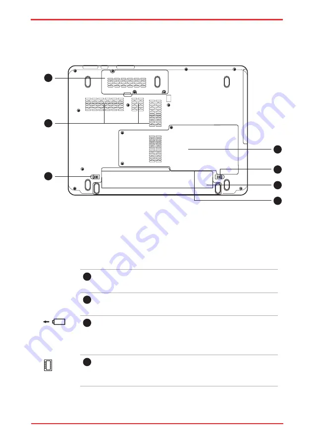
The following figure shows the underside of the computer. Make sure the display
is closed before turning over your computer.
1
Wireless LAN Module Cover
This cover protects the Wireless LAN module.
2
Cooling Vents
Cooling vents help prevent the CPU from overheating.
3
Battery Release Latch
Slide and hold this latch to release the battery pack for removal.
For detailed information on removing the battery pack, refer to
Chapter 6,
.
4
Hard Disk and Memory Module Cover
This cover protects the hard disk and the memory module. Refer
to the
The underside of the computer
1.
Wireless LAN Module cover
5.
Battery Pack Lock
2.
Cooling Vents
6.
Battery Pack
3.
Battery Release Latch
7.
SIM card slot* (Under the battery pack)
4.
HDD/Memory Module cover
2
6
4
3
5
1
7
Summary of Contents for Satellite Pro U500
Page 1: ...User s Manual Satellite U500 U500D Satellite Pro U500 U500D PORTÉGÉ M900 M900D ...
Page 12: ...User s Manual xii This label is located on the module A06 5003201 A05 0025001 ...
Page 30: ...User s Manual xxx ...
Page 48: ...User s Manual 1 18 Introduction ...
Page 64: ...User s Manual 2 16 ...
Page 124: ...User s Manual 4 48 Operating Basics ...
Page 132: ...User s Manual 5 8 The Keyboard ...
Page 162: ...User s Manual 8 14 Optional Devices ...
Page 184: ...User s Manual 9 22 Troubleshooting ...
Page 188: ...User s Manual B 2 Display Controller ...
Page 192: ...User s Manual C 4 Wireless LAN ...
Page 198: ...User s Manual E 4 TOSHIBA PC Health Monitor ...


