4 Replacement Procedures
4.7 Top Cover
4
1
4.7 Top Cover
Removing the Top Cover
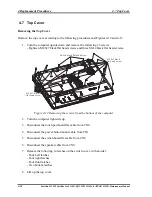
Remove the top cover according to the following procedures and Figures 4-12 and 4-13.
1.
Turn the computer upside down and remove the following 23 screws:
- Eighteen M2.5x7 black flat head screws and three M2x4 black flat head screws.
M2 5x4 black flat head screw
.
M2 5x7 black
flat head screw
.
M2 5x7 black
flat head screw
.
Figure 4-12 Removing the screws from the bottom of the computer
2.
Turn the computer right side up.
3.
Disconnect the touch pad board flat cable from CN8.
4.
Disconnect the power button board cable from CN1.
5.
Disconnect the switch board flat cable from CN2.
6.
Disconnect the speaker cable from CN9.
7.
Release the following 14 latches on the switch cover, in that order:
- Four Left latches
- Four right latches
- Four front latches
- Two bottom latches
8.
Lift up the top cover.
4-28
Satellite L350D/ Satellite Pro L350D/ EQUIUM L350D/ SATEGO L350D
Maintenance Manual
Summary of Contents for Satellite L350D series
Page 13: ...Chapter 1 Hardware Overview ...
Page 63: ...Chapter 3 Diagnostic Programs ...
Page 66: ......
Page 130: ...Chapter 4 Replacement Procedures 4 1 ...
Page 193: ...6000 1 次 Appendices ...

