23
TOSHIBA
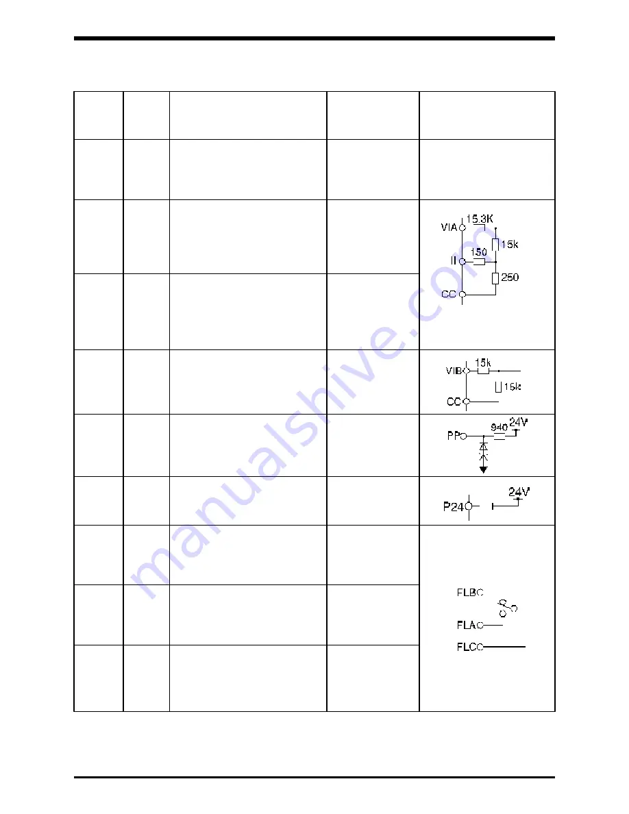
Standard Control Terminal Connections and Functions (cont'd)
Control common signal (not
connected to the fault output).
Both CC terminals are
connected together.
Frequency reference (4-20mA).
Used to set output frequency via
a 4-20mA current signal supplied
from the user’s controller. Cannot
be used with the VIA signal.
Frequency reference (0-10V).
Used to set output frequency via
a 0-10V voltage signal supplied
from the user’s controller. Cannot
be used with the II signal.
Frequency reference (0-10V).
Used to set output frequency via
a 0-10V voltage signal supplied
from the user’s controller.
Power supply for the external
potentiometer
Power supply for the external
relay
Fault output. Connected with
the FLC terminal if a fault occurs
(normally open).
Fault output. Connected with
the FLC terminal in the normal
condition (normally closed).
Fault latch output. A common
terminal for FLA and FLB.
10 Vdc, (Connect-
able potentiometer:
1k to 10k ohm,
1/4 W).
CC
Common
Terminal
block
name
I/O
Function
Electric rating
Inverter internal circuit
4 to 20 mA (Input
impedance: 400
ohm)
II
I
250 Vac, 2 A
VIA
VIB
PP
P24
I
I
O
FLC
FLB
FLA
O
O
O
O
30 Vdc, 2 A
resistive load
30 Vdc, 1.5 A
0 to 10 V (Input
impedance: 35.55
kohm)
0 to 10 V (Input
impedance: 30
kohm)
24 Vdc, 100 mA
inductive load


