*a: for RD-XS34SB, b: for RD-XS34SF, c: for RD-XS34SG
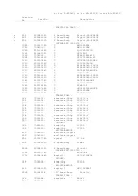
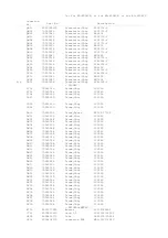
Location
No.
Part No.
Description
- MECHANICAL PARTS -
HDD1
P000428190
HDD,ST3160022ACECS 160GB
! RAM1
P000432490
DVD-RAM SW-9573-ETS
W051
P000433820
Cable,Flexible FFC,40P,L280
W051A
P000391300
CONV Unit,ATAPI-FFC
W052
P000435000
Cable,Flexible FFC,18P,L120
W053
P000434990
Cable,Flexible FFC,7P,L400
W055
P000387340
Cable,Flexible FFC,40P,L360
W055A
P000391300
CONV Unit,ATAPI-FFC
W056
P000435030
Cable,Flexible FFC,13P,L70
a
ZF01
P000405140
Remote Control UnitSE-R0132,RD-XS34SB
b,c
ZF01
P000405350
Remote Control UnitSE-R0133,RD-XS34SG/F
a
! ZF10A
P000422540
Owners Manual,ST English,RD-XS34SB
a
! ZF10B
P000422550
Owners Manual,OP English,RD-XS34SB
a
! ZF10C
P000422560
Owners Manual,Quick,English,RD-XS34SB
b
! ZF10D
P000422860
Owners Manual,Quick,English,RD-XS34SF
b
! ZF10G
P000422570
Owners Manual,ST English,RD-XS34SF
b
! ZF10I
P000422580
Owners Manual,OP English,RD-XS34SF
b
! ZF10K
P000422590
Owners Manual,ST French,RD-XS34SF
b
! ZF11A
P000422600
Owners Manual,OP French,RD-XS34SF
c
! ZF10E
P000422870
Owners Manual,Quick,English,RD-XS34SG
c
! ZF11B
P000422610
Owners Manual,ST English,RD-XS34SG
c
! ZF11C
P000422620
Owners Manual,OP English,RD-XS34SG
c
! ZF11D
P000422630
Owners Manual,ST German,RD-XS34SG
c
! ZF11E
P000422640
Owners Manual,OP German,RD-XS34SG
c
! ZF11G
P000422650
Owners Manual,ST Spanish,RD-XS34SG
c
! ZF11I
P000422660
Owners Manual,OP Spanish,RD-XS34SG
a
! ZF23
79088034
Power Cord,UK
b,c ! ZF23
79088010
Power Cord,TE
ZF23A
P000440210
FILTER, ZCAT2132-1130
ZF35
P000401300
IR-Blaster RWS1000-0052L
a
ZG01
P000435020
Panel Assy,Front RD-XS34SB
b,c
ZG01
P000435090
Panel Assy,Front RD-XS34SG/F
ZG20
P000432500
Cover,Top
a
ZG20A
P000438110
Rating Label RD-XS34SB
b,c
ZG20A
P000438120
Rating Label RD-XS34SG/F
ZG45
P000401260
Fan,DC 5025LL12SND2
ZG50
P000438100
Damper
Note:
A clamp filter (ZF23A) is attached to a power cord (ZF23). When replacing the
power cord, install the clamp filter.
There is a rating label (ZG20A) applied on the top cover (ZG20).
When the top cover is replaced with a new one, put a new rating label on the new
top cover.
Transcribe the following items (Model No., serial No., power supply/power
requirement etc.) described on the old rating label to the new rating label by
using a permanent marker.
2. PARTS LIST
Summary of Contents for RD-XS34SB
Page 30: ...1 1 SHIBAURA 1 CHOME MINATO KU TOKYO 105 8001 JAPAN ...
Page 60: ...1 1 SHIBAURA 1 CHOME MINATO KU TOKYO 105 8001 JAPAN ...
Page 67: ...1 3 4 A B C D E G 2 5 F 4 2 Front Circuit Diagram 4 2 1 Front Jack Circuit Diagram Fig 3 4 2 ...
Page 68: ...10 1 3 4 A B C D E G 2 5 6 7 8 9 F Fig 3 4 3 4 2 2 Front Circuit Diagram L R ...
Page 69: ...Fig 3 4 4 4 3 Digital Circuit Diagram 4 3 1 Digital 1 Circuit Diagram ...
Page 70: ...4 3 Digital Circuit Diagram 4 3 1 Digital 1 Circuit Diagram ...
Page 71: ......
Page 72: ......
Page 73: ......
Page 74: ......
Page 75: ......
Page 76: ......
Page 77: ...Fig 3 4 4 ...
Page 78: ...Fig 3 4 5 4 3 2 Digital 2 Circuit Diagram ...
Page 79: ...4 3 2 Digital 2 Circuit Diagram ...
Page 80: ......
Page 81: ......
Page 82: ......
Page 83: ......
Page 84: ...Fig 3 4 5 ...
Page 86: ...10 1 3 4 A B C D E G 2 5 6 7 8 9 F 4 4 2 Timer Circuit Diagram Fig 3 4 7 ...
Page 89: ...10 1 3 4 A B C D E G 2 5 6 7 8 9 F Fig 3 4 10 4 4 5 MSP Circuit Diagram ...
Page 90: ...1 3 4 A B C D E G 2 5 F 4 5 Tuner Unit Circuit Diagram Fig 3 4 11 ...
Page 95: ...1 2 3 4 5 6 7 A B C D E F 5 6 Mother PC Board Fig 3 5 11 EU05 Mother PC Board Top side ...


