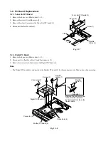
1-2-3. Mother PC Board
1. Remove the Front panel. (Refer to item 1-1-3.)
2. Remove the Rear panel. (Refer to item 1-1-5.)
3. Remove the Tuner Unit PC board. (Refer to item 1-2-1.)
4. Remove the Digital PC board. (Refer to item 1-2-2.)
5. Disconnect the flexible cable (1) and the connector (2).
6. Remove six screws (3), then remove the Mother PC board (4).
Fig. 2-1-9
Screws (3)
Connector (2)
Flexible cable (1)
Mother PC board (4)
Summary of Contents for RD-XS34SB
Page 30: ...1 1 SHIBAURA 1 CHOME MINATO KU TOKYO 105 8001 JAPAN ...
Page 60: ...1 1 SHIBAURA 1 CHOME MINATO KU TOKYO 105 8001 JAPAN ...
Page 67: ...1 3 4 A B C D E G 2 5 F 4 2 Front Circuit Diagram 4 2 1 Front Jack Circuit Diagram Fig 3 4 2 ...
Page 68: ...10 1 3 4 A B C D E G 2 5 6 7 8 9 F Fig 3 4 3 4 2 2 Front Circuit Diagram L R ...
Page 69: ...Fig 3 4 4 4 3 Digital Circuit Diagram 4 3 1 Digital 1 Circuit Diagram ...
Page 70: ...4 3 Digital Circuit Diagram 4 3 1 Digital 1 Circuit Diagram ...
Page 71: ......
Page 72: ......
Page 73: ......
Page 74: ......
Page 75: ......
Page 76: ......
Page 77: ...Fig 3 4 4 ...
Page 78: ...Fig 3 4 5 4 3 2 Digital 2 Circuit Diagram ...
Page 79: ...4 3 2 Digital 2 Circuit Diagram ...
Page 80: ......
Page 81: ......
Page 82: ......
Page 83: ......
Page 84: ...Fig 3 4 5 ...
Page 86: ...10 1 3 4 A B C D E G 2 5 6 7 8 9 F 4 4 2 Timer Circuit Diagram Fig 3 4 7 ...
Page 89: ...10 1 3 4 A B C D E G 2 5 6 7 8 9 F Fig 3 4 10 4 4 5 MSP Circuit Diagram ...
Page 90: ...1 3 4 A B C D E G 2 5 F 4 5 Tuner Unit Circuit Diagram Fig 3 4 11 ...
Page 95: ...1 2 3 4 5 6 7 A B C D E F 5 6 Mother PC Board Fig 3 5 11 EU05 Mother PC Board Top side ...


