– 88 –
No.
Part name
Procedure
Remarks
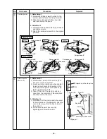
1. Detachment
1) Recover the refrigerant gas and then
remove the refrigerant pipe of the indoor
unit.
2) Perform works of 1 of
i
.
3) Pull out TC sensor and TCJ sensor wirings
from the holder.
4) Remove the screws (Ø4 x 8, 2 pcs.) and
then remove the piping cover.
5) Remove screws (Ø4 x 8, 1pc.) of the heat
exchanger fixed plate.
6) While holding the heat exchanger, remove
the fixed screws (Ø4 x 8, 2 pcs.) of the end
plate and then take out the heat exchanger
slowly.
2. Attachment
1) Set the heat exchanger at the original
position and fix it as before, using screws
which removed the end plate, heat
exchanger fixed plate and piping cover.
2) Enter TC sensor and TCJ sensor wirings in
the holder and then perform wirings as
original.
3) Attach the drain pan and the bottom base
as original.
Heat
exchanger
k
: Screw position
40 Type
80 Type
140 Type
End plate
End plate
End plate
Heat exchanger
fixed plate
Heat exchanger
fixed plate
Heat exchanger
fixed plate
Piping cover
Piping cover
Piping
cover
Summary of Contents for RAV-SM1106BT-E
Page 18: ... 18 ...
Page 19: ... 19 3 WIRING DIAGRAM ...
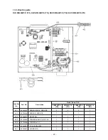
Page 34: ... 34 5 3 Indoor Print Circuit Board MCC 1631 ...
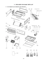
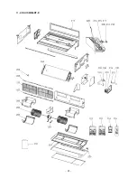
Page 89: ... 89 11 EXPLODED VIEWS AND PARTS LIST 11 1 RAV SM406BT E RAV SM456BT E RAV SM566BT E ...
Page 91: ... 91 11 2 RAV SM806BT E ...
Page 93: ... 93 11 3 RAV SM406BT TR RAV SM456BT TR RAV SM566BT TR ...
Page 95: ... 95 11 4 RAV SM806BT TR ...
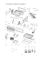
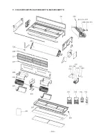
Page 98: ... 98 11 6 RAV SM1106BT E RAV SM1406BT E RAV SM1606BT E ...
Page 100: ... 100 11 7 RAV SM1106BT TR RAV SM1406BT TR RAV SM1606BT TR ...


