


– 2 –
NOTE
A direct current motor is adopted for indoor fan motor in the Concealed Duct Standard Type air conditioner.
Caused from its characteristics, a current limit works on the direct current motor. When replacing the
high-performance filter or when opening the service board, be sure to stop the fan. If an above action is
executed during the fan operation, the protective control works to stop the unit operation, and the check code
“P12” may be issued. However it is not a trouble. When the desired operation has finished, be sure to reset
the system to clear “P12” error code using the leak breaker of the indoor unit. Then push the operation stop
button of the remote controller to return to the usual operation.
CONTENTS
Original instruction ......................................................................................... 4
Warning Indications on the Air Conditioner Unit ........................................ 6
Precaution for Safety ...................................................................................... 7
New Refrigerant (R410A) .............................................................................. 14
1. Safety Caution Concerned to New Refrigerant ..................................................... 14
2. Cautions on Installation/Service ............................................................................ 14
3. Pipe Materials .......................................................................................................... 14
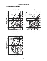
1. AIR DUCTING WORK ............................................................................. 16
1-1. Static Pressure Characteristics ....................................................................... 16
2. CONSTRUCTION VIEWS (EXTERNAL VIEWS).................................... 17
3. WIRING DIAGRAM .................................................................................. 19
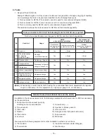
4. SPECIFICATIONS OF ELECTRICAL PARTS ....................................... 20
5. CONTROL BLOCK DIAGRAM ............................................................... 21
5-1. Indoor Controller Block Diagram..................................................................... 21
5-2. Control Specifications ...................................................................................... 24
5-3. Indoor Print Circuit Board ................................................................................ 34
6. TROUBLESHOOTING ............................................................................ 36
6-1. Summary of Troubleshooting .......................................................................... 36
6-2. Check Code List (Indoor) ................................................................................. 41
6-3. Diagnostic Procedure for Each Check Code (Indoor Unit) ........................... 46
7. REPLACEMENT OF SERVICE P.C. BOARD......................................... 58
7-1. Indoort Unit ....................................................................................................... 58
Summary of Contents for RAV-SM1106BT-E
Page 18: ... 18 ...
Page 19: ... 19 3 WIRING DIAGRAM ...
Page 34: ... 34 5 3 Indoor Print Circuit Board MCC 1631 ...
Page 89: ... 89 11 EXPLODED VIEWS AND PARTS LIST 11 1 RAV SM406BT E RAV SM456BT E RAV SM566BT E ...
Page 91: ... 91 11 2 RAV SM806BT E ...
Page 93: ... 93 11 3 RAV SM406BT TR RAV SM456BT TR RAV SM566BT TR ...
Page 95: ... 95 11 4 RAV SM806BT TR ...
Page 98: ... 98 11 6 RAV SM1106BT E RAV SM1406BT E RAV SM1606BT E ...
Page 100: ... 100 11 7 RAV SM1106BT TR RAV SM1406BT TR RAV SM1606BT TR ...