background image

42-EN

41-EN

– 21 –

15

Appendix

[1] Existing piping

Work instructions

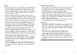
The existing R22 and R410A piping can be reused for 
our digital inverter R32 product installations.

 WARNING

Con

fi

rming the existence of scratches or dents on 

the existing pipes and con

fi

rming the reliability of 

the pipe strength are conventionally referred to the 
local site.
If the speci

fi

ed conditions can be cleared, it is 

possible to update existing R22 and R410A pipes 
to those for R32 models.

Basic conditions needed to reuse existing 
pipes

Check and observe the presence of three conditions in 
the refrigerant piping works.
1. 

Dry

 (There is no moisture inside of the pipes.)

2. 

Clean

 (There is no dust inside of the pipes.)

3. 

Tight

 (There are no refrigerant leaks.)

Restrictions for use of existing pipes

In the following cases, the existing pipes should 
not be reused as they are. Clean the existing pipes 
or exchange them with new pipes.

1. When a scratch or dent is heavy, be sure to use 

new pipes for the refrigerant piping works.

2. When the existing pipe thickness is thinner than the 

speci

fi

ed “Pipe diameter and thickness,” be sure to 

use new pipes for the refrigerant piping works.


y

The operating pressure of R32 is high. If there is 
a scratch or dent on the pipe or a thinner pipe is 
used, the pressure strength may be inadequate, 
which may cause the pipe to break in the worst 
case.

*  Pipe diameter and thickness (mm)

Pipe outer diameter

Ø6.4 Ø9.5 Ø12.7 Ø15.9 Ø19.0

Thickness

R32/R410A

0.8

0.8

0.8

1.0

1.0

R22


y

In case the pipe diameter is Ø12.7 mm or less 
and the thickness is less than 0.7 mm, be sure to 
use new pipes for the refrigerant piping works.

3. When the outdoor unit was left with the pipes 

disconnected, or the gas leaked from the pipes and 
the pipes were not repaired and re

fi

lled.


y

There is the possibility of rain water or air, 
including moisture, entering the pipe.

4. When refrigerant cannot be recovered using a 

refrigerant recovery unit.


y

There is the possibility that a large quantity of dirty 
oil or moisture remains inside the pipes.

5. When a commercially available dryer is attached to 

the existing pipes.


y

There is the possibility that copper green rust has 
been generated.

6. When the existing air conditioner is removed after 

refrigerant has been recovered.

  Check if the oil is judged to be clearly different from 

normal oil.


y

The refrigerator oil is copper rust green in color:

  There is the possibility that moisture has mixed 

with the oil and rust has been generated inside 
the pipe.


y

There is discolored oil, a large quantity of residue, 
or a bad smell.


y

A large quantity of shiny metal dust or other wear 
residue can be seen in the refrigerant oil.

7. When the air conditioner has a history of the 

compressor failing and being replaced.


y

When discolored oil, a large quantity of residue, 
shiny metal dust, or other wear residue or mixture 
of foreign matter is observed, trouble will occur.

8. When temporary installation and removal of the air 

conditioner are repeated such as when leased etc.

9. If the type of refrigerator oil of the existing air 

conditioner is other than the following oil (Mineral 
oil), Suniso, Freol-S, MS (Synthetic oil), alkyl 
benzene (HAB, Barrel-freeze), ester series, PVE 
only of ether series.


y

The winding-insulation of the compressor may 
deteriorate.

NOTE

The above descriptions are results have been 
con

fi

rmed by our company and represent our views on 

our air conditioners, but do not guarantee the use of 
the existing pipes of air conditioners that have adopted 
R32 in other companies.

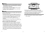
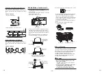
Curing of pipes

When removing and opening the indoor or outdoor unit 
for a long time, cure the pipes as follows:


y

Otherwise rust may be generated when moisture or 
foreign matter due to condensation enters the pipes.


y

The rust cannot be removed by cleaning, and new 
pipes are necessary.

Placement 

location

Term

Curing manner

Outdoors

1 month or more

Pinching

Less than 1 month

Pinching or taping

Indoors

Every time

14

Troubleshooting

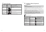
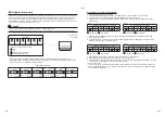
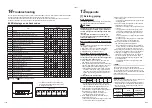
You can perform fault diagnosis of the outdoor unit with the LEDs on the P.C. Board of the outdoor unit in addition 
to using the check codes displayed on the wired remote controller of the indoor unit.
Use the LEDs and check codes for various checks. Details of the check codes displayed on the wired remote 
controller of the indoor unit are described in the Installation Manual of the indoor unit.


„

LED displays and check codes

No.

Error

Display

D800

D801

D802

D803

D804

D805

1

Normal

2

Discharge temperature sensor (TD) error

3

Heat exchanger temperature sensor (TE) error

4

Heat exchanger temperature sensor (TL) error

5

Outside temperature sensor (TO) error

6

Suction temperature sensor (TS) error

7

Heatsink temperature sensor (TH) error

8

Miss-mounting of sensor (TE, TS)

9

EEPROM error

10

Compressor breakdown

11

Compressor lock

12

Current detection circuit error

13

Case thermostat activated

14

Unset model type

15

Communication error between MCUs

16

Discharge temperature sensor error

17

High pressure SW error

18

Power supply voltage error

19

Heatsink overheating error

20

Gas leak detected

21

4-way valve reversal error

22

High pressure protective activated

23

Fan system error

24

Compressor driver device short circuit

25

Position detection circuit error

 : ON,    : OFF,    : Rapid 

fl

ashing (5 times/sec.)

LED displays

Service Switches

D800

D801

D803

D805

D802

D804

SW01

SW02

LED displays

D800

D801

D802

D803

D804

D805

(Yellow) (Yellow) (Yellow) (Yellow) (Yellow) (Green)

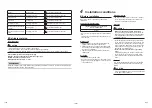
*  The LEDs and switches are located at the 

Sub P.C.Board of the outdoor unit as shown 
in the 

fi

gure on the left.

Summary of Contents for RAV-GV1101AT8P-E

Page 1: ...AIR CONDITIONER SPLIT TYPE Installation Manual Outdoor Unit Model name RAV GV1101AT8P E RAV GV1401AT8P E For commercial use English Heat Pump Model ...

Page 2: ...rigerant R32 which does not destroy the ozone layer This outdoor unit is designed exclusively for use with R32 refrigerant Be sure to use in combination with a R32 refrigerant indoor unit This equipment complies with IEC 61000 3 12 provided that the short circuit power Ssc is greater than or equal to Ssc 1 at the interface point between the user s supply and the public system It is the responsibil...

Page 3: ...ained and is thus thoroughly acquainted with the knowledge related to this work The qualified installer who is allowed to do the refrigerant handling and piping work involved in installation relocation and removal has the qualifications pertaining to this refrigerant handling and piping work as stipulated by the local laws and regulations and he or she is a person who has been trained in matters r...

Page 4: ... fire This mark is for R32 refrigerant only Refrigerant type is written on nameplate of outdoor unit In case that refrigerant type is R32 this unit uses a flammable refrigerant If refrigerant leaks and comes in contact with fire or heating part it will create harmful gas and there is risk of fire Read the OWNER S MANUAL carefully before operation Service personnel are required to carefully read th...

Page 5: ...ve gloves and safety work clothing and then proceed Do not climb onto or place objects on top of the outdoor unit You may fall or the objects may fall off of the outdoor unit and result in injury When working at heights use a ladder which complies with the ISO 14122 standard and follow the procedure in the ladder s instructions Also wear a helmet for use in industry as protective gear to undertake...

Page 6: ... wear shoes with additional protective toe caps When transporting the air conditioner do not take hold of the bands around the packing carton You may injure yourself if the bands should break Do not place any combustion appliance in a place where it is directly exposed to the wind of air conditioner otherwise it may cause imperfect combustion Do not install the air conditioner in a poorly ventilat...

Page 7: ...no circumstances must this work be done by an unqualified individual since failure to carry out the work properly may result in electric shocks and or electrical leaks The appliance shall be installed in accordance with national wiring regulations Capacity shortages of the power circuit or an incomplete installation may cause an electric shock or fire Use wiring that meets the specifications in th...

Page 8: ...stance and water drainage Then conduct a test run to check that the air conditioner is operating properly After the installation work confirm that refrigerant gas does not leak If refrigerant gas leaks into the room and flows near a fire source such as a cooking range noxious gas may be generated Explanations given to user Upon completion of the installation work tell the user where the circuit br...

Page 9: ...that water and or dust does not enter Cautions for outdoor unit installation space In the event that the outdoor unit is installed in a small space and refrigerant leaks accumulation of highly concentrated refrigerant may cause a fire hazard Therefore be sure to follow the installation space instructions in the Installation Manual and provide open space on at least one of the four outdoor unit sid...

Page 10: ...gly special tools are required for the R32 or R410A refrigerant units For connecting pipes use new and clean piping materials with high pressure fittings made for the R32 or R410A only so that water and or dust does not enter y When using existing piping refer to 15 Appendix 1 Existing piping Required Tools Equipment and Precautions for use Prepare the tools and equipment listed in the following t...

Page 11: ...ric shock If the outdoor unit is not properly earthed you may be exposed to an electric shock y Be sure to connect the earth wire grounding work Incomplete grounding can cause an electric shock Do not connect ground wires to gas pipes water pipes lightning rods or ground wires for telephone wires Test run Turn on the leakage breaker at least 12 hours before starting a test run to protect the compr...

Page 12: ...ain or direct sunlight y A location that does not increase the operating noise or vibration of the outdoor unit y A location that does not produce any drainage problems from discharged water Do not install the outdoor unit in the following locations y A location with a saline atmosphere coastal area or one that is full of sulfide gas hot spring area Special maintenance is required y A location sub...

Page 13: ... may cause dewing or dripping of water y When collectively draining discharged water completely use a drain pan Drain nipple Waterproof rubber cap 5 pcs Waterproof rubber cap Knockout hole Drain nipple For reference If a heating operation is to be continuously performed for a long time under the condition that the outdoor temperature is 0 C or lower draining defrosted water may be difficult due to...

Page 14: ...d 2 Tight connection between pipes and unit 3 Evacuate the air in the connecting pipes by using VACUUM PUMP 4 Check the gas leakage Connected points Piping connection Liquid side Outer diameter Thickness Ø9 5 mm 0 8 mm Gas side Outer diameter Thickness Ø15 9 mm 1 0 mm Knockout of pipe cover Knockout procedure Rear direction Side direction Down direction Front direction Pipe cover y The indoor outd...

Page 15: ...e a single crescent the flare nut cannot be tightened to the required tightening torque On the other hand use a single crescent to loosen or tighten the flare nut of the valve on the liquid side Unit N m Outer dia of copper pipe Tightening torque 9 5 mm dia 34 to 42 3 4 to 4 2 kgf m 15 9 mm dia 63 to 77 6 3 to 7 7 kgf m Loosened Cap Tightened Flare nut CAUTION y Do not put the crescent wrench on t...

Page 16: ... check the connections for leakage Check for leaks with foaming liquid etc take steps to fix the leaks such as brazing the pipes again and tightening the flare nuts and then perform the airtight test again After the airtight test is completed evacuate the nitrogen gas Air purge With respect to the preservation of the terrestrial environment adopt Vacuum pump to purge air Evacuate air in the connec...

Page 17: ...ured specially for HFC refrigerant R32 R410A R134a etc to perform the R32 gas leak inspection Indoor unit inspection locations piping connections Refrigerant piping Indoor unit side piping Outdoor unit inspection locations Leak detectors for conventional HCFC refrigerant R22 etc cannot be used as the sensitivity drops to approximately 1 40 when used for HFC refrigerant y R32 has a high working pre...

Page 18: ... the pipe valve fixing plate and cord clamps stored in the electric parts box Service panel Cord clamp Electric part box Pipe hole Wiring between indoor unit and outdoor unit The dashed lines show on site wiring Input power 380 415V 3N 50Hz 380V 3N 60Hz Indoor unit Outdoor unit Wired remote controller Circuit breaker y Connect the Indoor Outdoor connecting wires to the identical terminal number on...

Page 19: ...door outdoor units are strongly recommended As a general rule if an indoor unit is operated for about 8 hours daily the indoor outdoor units will need to be cleaned at least once every 3 months This cleaning and maintenance should be carried out by a qualified service person Failure to clean the indoor outdoor units regularly will result in poor performance icing water leaking and even compressor ...

Page 20: ...en to recover the refrigerant 1 Operate the indoor unit in the fan mode 2 Check that the LED displays are placed in their initial status If not place them in the initial status 3 Hold down SW01 for at least 5 seconds and check that D804 flashes slowly Fig 1 4 Press SW01 once to set the LED displays D800 to D805 to the refrigerant recovery LED display shown below Fig 2 Fig 1 Fig 2 LED displays indi...

Page 21: ...r at least 5 seconds to return to the initial status and then repeat the setting steps How to check the existing piping settings You can check whether the existing piping settings are enabled 1 Check that the LED displays are placed in their initial status If not place them in the initial status 2 Hold down SW01 for at least 5 seconds and check that D804 flashes slowly Fig 9 3 Press SW01 four time...

Page 22: ... When the air conditioner has a history of the compressor failing and being replaced y When discolored oil a large quantity of residue shiny metal dust or other wear residue or mixture of foreign matter is observed trouble will occur 8 When temporary installation and removal of the air conditioner are repeated such as when leased etc 9 If the type of refrigerator oil of the existing air conditione...

Page 23: ...essary to change the flare nut machining size due to pipe compression 1 Flare nut width H H mm Copper pipe outer diameter Ø6 4 Ø9 5 Ø12 7 Ø15 9 Ø19 0 For R32 R410A 17 22 26 29 36 For R22 Same as above 24 27 Same as above 2 Flare machining size A A mm Copper pipe outer diameter Ø6 4 Ø9 5 Ø12 7 Ø15 9 Ø19 0 For R32 R410A 9 1 13 2 16 6 19 7 24 0 For R22 9 0 13 0 16 2 19 4 23 3 Becomes a little larger ...

Page 24: ... becomes invalid if technical or operational modifications are introduced without the manufacturer s consent Declaration of conformity Manufacturer Toshiba Carrier Thailand Co Ltd 144 9 Moo 5 Bangkadi Industrial Park Tivanon Road Tambol Bangkadi Amphur Muang Pathumthani 12000 Thailand TCF holder TOSHIBA CARRIER UK LTD Porsham Close Belliver Industrial Estate Roborough Plymouth Devon PL6 7DB United...

Page 25: ...t leaks may be required depending on European or local legislation 7 Contact dealers installers etc for any questions Fill in the label as follows Pre charged refrigerant at factory kg specified in the nameplate Additional charge on installation site kg GWP kg 1000 Warnings on refrigerant leakage Check of concentration limit The room in which the air conditioner is to be installed requires a desig...

Page 26: ...1131850101 144 9 Moo 5 Bangkadi Industrial Park Tivanon Road Tambol Bangkadi Amphur Muang Pathumthani 12000 Thailand ...

Reviews: