


– 95 –
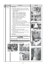
Interface
b
oard
Fan-IPDU
b
oard
U
s
ing the hook,
it i
s
po
ss
i
b
le to temporarily
sus
pend
the inverter a
ss
em
b
ly (front).
Screw
s
(2 po
s
ition
s
)
Inverter a
ss
em
b
ly (front)
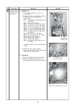
U
s
ing
Noi
s
e filter
b
oard
State of noi
s
e
filter
b
oard
when removed
State of noi
s
e
filter
b
oard
when removed
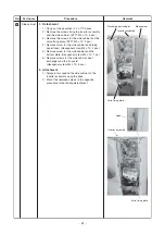
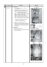
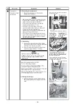
No.
7
Part name
Noi
s
e filter
b
oard
MCC-1600
Procedure
1. Detachment
1) Perform the operation in 1. of
,1. of
,
1.-2 of
and 1.-2 of
.
2) Remove the
s
crew
s
(3 po
s
ition
s
) fixing the inverter a
ss
em-
b
ly (front). Then
s
lide the inverter a
ss
em
b
ly (front)
u
pwardly
and remove.
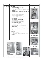
3) Remove the lead wire
s
connector to other component
s
from
the noi
s
e filter
b
oard.
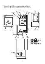
CN05 : Power
su
pply terminal
b
lock (red)
CN06 : Power
su
pply terminal
b
lock (White)
CN07 : Power
su
pply terminal
b
lock (Black)
CN08 : Power
su
pply terminal
b
lock (Gray)
CN09 : Connection to earth (Brown)
CN10 : Po
s
i
s
tor (Red)
CN16 : Relay (Red)
CN17 : Compre
ss
or IPDU
b
oard (White)
CN18 : Relay (Black)
CN19 : Relay (Gray)
CN20 : Power
su
pply terminal
b
lock (White)
CN23 : Fan-IPDU
b
oard (5P, Red)
CN50 : Interface
b
oard (2P, White)
CN51 : Fan-IPDU
b
oard (2P, Back)
∗
Connector
s
s
ho
u
ld
b
e removed after
u
nlocking the
ho
us
ing
s
ection.
4) Remove the claw of the
su
pport (2 po
s
ition
s
) and the
s
crew
(2 po
s
ition
s
) fixing the
b
a
s
e and then remove the noi
s
e filter
b
a
s
e.
2. Attachment
1) Mo
u
nt noi
s
e filter
b
oard.
2) Mo
u
nt component
s
in the oppo
s
ite method to that when
removing.
Remarks


