


– 57 –
8-2. Diagnostic Procedure for Each Check Code (Outdoor Unit)
1) This section describes the diagnostic method for each check code displayed on the remote controller.
2) In some cases, a check code indicates multiple symptoms.
In this case, confirm LED display on the outdoor P.C. board to narrow the contents to be confirmed.
3) The display on the remote controller may differ from that of LED.
The check code on the remote controller is displayed only when the same trouble occurred continuously by
multiple times while LED of the outdoor P.C. board is displayed when a trouble occurred once.
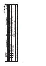
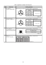
LED display on outdoor P.C. board
Dip switch setup
• When t
u
rning on 1) only of SW803, the late
s
t tro
ub
le
i
s
di
s
played. A
s
the memory i
s
s
tored, it can
b
e
confirmed even if the power
su
pply i
s
t
u
rned off
once. (excl
u
ding o
u
t
s
ide temp.
s
en
s
or (TO) tro
ub
le)
• When the work fini
s
hed or the o
u
tdoor temp.
s
en
s
or (TO) tro
ub
le wa
s
fo
u
nd, t
u
rn off all of SW803.
(The tro
ub
le which occ
u
r
s
at pre
s
ent i
s
di
s
played.)
Display selection
• When even a LED of D800 to D804 (Yellow)
goe
s
on, tro
ub
le occ
u
rrence i
s
indicated.
<Display 1>
• If p
us
hing the
bu
tton
s
witch SW800 for 1
s
econd
u
nder the a
b
ove condition, the yellow LED i
s
di
s
played with fla
s
hing.
<Display 2>
• When p
us
hing SW800 for 1
s
econd again, the
s
tat
us
ret
u
rn
s
to
<Display 1>
.
• The tro
ub
le content
s
can
b
e confirmed
b
y com
b
ining
<Display 1>
and
<Display 2>
.
<Display 1>
<Display 2>
(No tro
ub
le)
(P
us
h SW800)
(Tro
ub
le occ
u
rred)
D805 (Green)
D804 (Yellow)
D803 (Yellow)
D802 (Yellow)
D801 (Yellow)
D800 (Yellow)
(Example of di
s
charge temp.
s
en
s
or tro
ub
le)
: Go off,
: Go on,
: Fla
s
h
<Latest trouble display>
Only 1) of SW803 i
s
ON.
<Trouble display, which occurs at present>
All SW803 are OFF. (Initial
s
tat
us
)
ON
1 2 3 4
ON
1 2 3 4
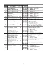
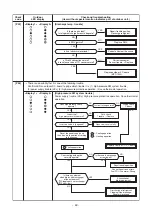
Check "check code [14]".
Correct wiring of connector
s
and terminal
b
lock
s
.
Replace o
u
tdoor P.C.
b
oard (MCC-1599).
Correct wiring
and inter-
u
nit ca
b
le.
I
s
s
etting of gro
u
p addre
ss
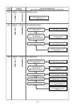
of remote controller correct?
Are inner wiring and
inter-
u
nit ca
b
le
s
(1, 2, 3) normal?
Are connection of CN01 of MCC-1599 and
wiring of terminal
b
lock
s
(1, 2, 3) normal?
Replace indoor P.C.
b
oard.
Doe
s
D502 (Orange LED) fla
s
h after
power
su
pply i
s
t
u
rned on again?
YES
YES
YES
YES
NO
NO
NO
NO
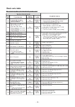
Check
code
[E04]
Outdoor
LED display
—
Check and troubleshooting
(Item without special mention Indicates part of outdoor unit.)
[Indoor/Outdoor communication trouble]


