


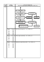


– 54 –
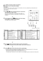
Operation of dia
g
no
s
tic function
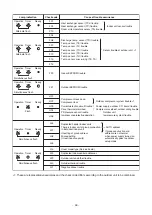
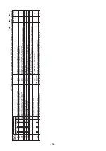
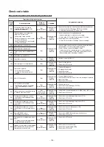
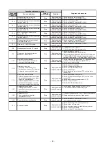
Check code
S
tatu
s
of
air conditioner
Condition
Cau
s
e of operation
Jud
g
ment and mea
s
ure
s
Indoor unit
F04
Disconnection, short-circuit of
disch
a
rge temp. sensor (TD)
S
top
Displ
a
yed when
trouble is detected
1. Check disch
a
rge temp. sensor (TD).
2. Check outdoor P.C. bo
a
rd (MCC-15
99
).
F06
Disconnection, short-circuit of outdoor
temp. sensor (TE)
S
top
Displ
a
yed when
trouble is detected
1. Check temp. sensor (TE).
2. Check outdoor P.C. bo
a
rd (MCC-15
99
).
F07
Disconnection, short-circuit of outdoor
temp. sensor (TL)
S
top
Displ
a
yed when
trouble is detected
1. Check temp. sensor (TL).
2. Check outdoor P.C. bo
a
rd (MCC-15
99
).
F12
Disconnection, short-circuit of suction
temp. sensor (T
S
)
S
top
Displ
a
yed when
trouble is detected
1. Check suction temp. sensor (T
S
).
2. Check outdoor P.C. bo
a
rd (MCC-15
99
).
F15
Miss-mounting of outdoor temp.
sensor (TE, T
S
)
S
top
Displ
a
yed when
trouble is detected
1. Check temp. sensor (TE, T
S
).
2. Check outdoor P.C. bo
a
rd (MCC-15
99
).
F0
8
Disconnection, short-circuit of outside
temp. sensor (TO)
Continue
Displ
a
yed when
trouble is detected
1. Check outside temp. sensor (TO).
2. Check outdoor P.C. bo
a
rd (MCC-15
99
).
F1
3
Disconnection, short-circuit of he
a
t
sink temp. sensor (TH)
S
top
Displ
a
yed when
trouble is detected
L2
9
Communic
a
tion trouble between
outdoor P.C. bo
a
rd MCU
S
top
Displ
a
yed when
trouble is detected
1. Check outdoor P.C. bo
a
rd (MCC-15
99
).
(Q201 is incorpor
a
ted in TH sensor.)
F
3
1
Outdoor P.C. EEPROM trouble
S
top
Displ
a
yed when
trouble is detected
1. Check outdoor P.C. bo
a
rd (MCC-15
99
).
L10
Unset jumper of service P.C. bo
a
rd
S
top
Displ
a
yed when
trouble is detected
1. Outdoor service P.C. bo
a
rd
Check model type setting jumper wire.
1. Check outdoor P.C. bo
a
rd
(MCC-15
9
6, MCC-15
9
7, MCC-15
99
).
2. Connection check between CN
8
02 of MCC-15
99
a
nd
CN504 of MCC-15
9
7,
a
nd
a
lso connection check
between CN505 of MCC-15
9
7
a
nd CN
8
51 of MCC-15
9
6.
F2
3
Ps sensor trouble
S
top
Displ
a
yed when
trouble is detected
1. Check connection of Ps sensor connector.
2. Check f
a
ilure of Ps sensor.
3
. Check compressing power trouble of compressor.
4. Check 4-w
a
y v
a
lve trouble.
5. Check outdoor P.C. bo
a
rd trouble.
P07
He
a
t sink overhe
a
t trouble
∗
He
a
t sink temp. sensor detected
over specified temper
a
ture.
S
top
Displ
a
yed when
trouble is detected
1. Check screw tightening between PC. Bo
a
rd
a
nd he
a
t
sink
a
nd check r
a
di
a
tor gre
a
se (MCC-15
99
).
2. Check he
a
t sink bl
a
st p
a
th.
H02
Compressor lock
∗
Over-current detection
a
fter
compressor st
a
rt-up
S
top
Displ
a
yed when
trouble is detected
1. Trouble of compressor (Lock, etc.): Repl
a
ce compressor.
2. Wiring trouble of compressor (Open ph
a
se)
H0
3
Current detection circuit trouble
S
top
Displ
a
yed when
trouble is detected
1. Check outdoor P.C. bo
a
rd (MCC-15
99
).
(AC current detection circuit)
P15
Detection of g
a
s le
a
k
∗
Disch
a
rge temp. sensor (TD),
S
uction temp. sensor (T
S
) detected
temper
a
ture over specified temp.
S
top
Displ
a
yed when
trouble is detected
1. Check g
a
s le
a
k, rech
a
rge
2. Check full open of service v
a
lve.
3
. Check PMV (Pulse Motor V
a
lve).
4. Check broken pipe.
5. Check disch
a
rge temp. sensor (TD), suction temp.
sensor (T
S
).
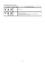
P1
9
4-w
a
y v
a
lve inverse trouble
∗
After he
a
ting oper
a
tion h
a
s st
a
rted,
indoor he
a
t exch
a
nger temp. lowers
under the specified temp.
∗
After he
a
ting oper
a
tion h
a
s st
a
rted,
outdoor he
a
t exch
a
nger / suction
temp. rises over the specified temp.
S
top
Displ
a
yed when
trouble is detected
1. Check oper
a
tion of 4-w
a
y v
a
lve.
2. Check outdoor he
a
t exch
a
nger (TE), suction temp.
sensor (T
S
).
3
. Check indoor he
a
t exch
a
nger sensor (TC).
4. Check 4-w
a
y v
a
lve coil.
5. Check PMV (Pulse Motor V
a
lve).
H01
Compressor bre
a
k down
∗
Although oper
a
tion h
a
s st
a
rted,
oper
a
tion frequency decre
a
ses
a
nd
oper
a
tion stops.
S
top
Displ
a
yed when
trouble is detected
1. Check power supply volt
a
ge. (AC
3
42 to 457V)
2. Overlo
a
d oper
a
tion of refriger
a
ting cycle


