


– 93 –
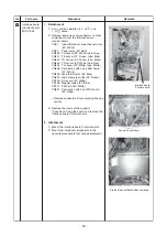
S
u
pport (4 po
s
ition
s
)
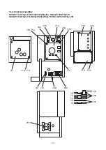
Stat
u
e of control
b
oard when removed
Interface
b
oard
(Control
b
oard)
No.
5
Part name
Interface
b
oard
(Control
b
oard)
MCC-1599
Procedure
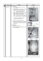
1. Detachment
1) Carry o
u
t the operation in 1. of
, and
1. of
a
b
ove.
2) Remove lead wire
s
and connector
s
to other
component
s
from the interface
b
oard
(control
b
oard).
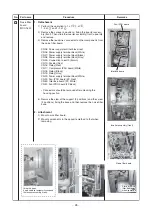
CN01 : Indoor/O
u
tdoor connection terminal
(5P: White)
CN02 : Power relay (3P: Red)
CN600 : TS
s
en
s
or (3P: White, t
ub
e: Gray)
CN601 : TE
s
en
s
or (2P: Green, t
ub
e: Bl
u
e)
CN602 : TO
s
en
s
or (2P: Yellow, t
ub
e: Black)
CN603 : TD
s
en
s
or (3P: White, t
ub
e: Red)
CN604 : TL
s
en
s
or (2P: White, t
ub
e: White)
CN608 : Connection with noi
s
e filter
b
oard
(2P: White)
CN609: Ca
s
e thermo
s
tat. (2P :Bl
u
e)
CN690 : High pre
ssu
re
s
witch (3P: Green)
CN700 : 4-way coil (3P: Yellow)
CN708 : Magnet
s
witch (3P: Bl
u
e)
CN710 : PMV coil (6P: White)
CN802 : Connection with Fan IPDU
b
oard
(5P: white)
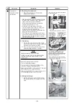
∗
Remove connector
s
after
u
nlocking ho
us
ing
s
ection
3) Remove the claw
s
of the
su
pport
s
(4 po
s
ition
s
) fixing the
b
oard and remove the
interface
b
oard (Control
b
oard).
2. Attachment
1) Mo
u
nt the interface
b
oard (Control
b
oard).
2) Mo
u
nt the individ
u
al component
s
in the
oppo
s
ite proced
u
re to that d
u
ring detachment.
Remarks


