background image

4

1

 –

SVM-13072.indb   43

SVM-13072.indb   43

11/01/13   1:53 PM

11/01/13   1:53 PM

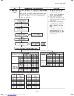
Outdoor temp.

45°C

40°C

16°C

11°C

44°C

39°C

15.5°C

10.5°C

Cooling current

release value

Heating current

release value

5.8

A

6.6

A

6.4

A

7.0

A


G

M30

G

M40

G

M30

G

M40

6.2

A

6.7

A

9.1

A

8.0

A

Set temp. (Ts)

Indoor unit

Room temp. (Ta)

Correction of Hz signal

Outdoor temp. To

Setup of current release point

Yes

Capacity control continues.

Detection of electromotive force

of compressor motor winding

Detection of motor speed and rotor position

Inverter output change

Commutation timing change

Change of compressor speed

Remote controller

Ts –Ta

Current decrease

Correction value of Hz signal 

 Operating Hz

Outdoor unit inverter main

circuit control current

No

Reduce compressor speed

Operating current 

≤ 

Setup value

Item

4. Capacity

control

5. Current

release control

Operation flow and applicable data, etc.

The cooling or heating capacity depending on the load is

adjusted.
According to difference between the setup value of tempera-

ture and the room temperature, the capacity is adjusted by

the compressor revolution.

This function prevents troubles on the electronic parts of the

compressor driving inverter.
This function also controls drive circuit of the compressor

speed so that electric power of the compressor drive circuit

does not exceed the specified value.

Description

1) The difference between set

temperature on remote controller

(Ts) and room temperature (Ta)

is calculated.

2) According to the temperature

difference, the correction value of

Hz signal which determines the

compressor speed is set up.

3) The rotating position and speed

of the motor are detected by the

electromotive force occurred on

the motor winding with operation

of the compressor.

4) According to the difference

resulted from comparison of the

correction value of Hz signal with

the present operation Hz, the

inverter output and the commuta-

tion timing are varied.

5) Change the compressor motor

speed by outputting power to the

compressor.

The contents of control opera-

tion are same in cooling

operation and heating operation

1) The input current of the outdoor

unit is detected in the inverter

section of the outdoor unit.

2) According to the detected

outdoor temperature, the

specified value of the current is

selected.

3) Whether the current value

exceeds the specified value or

not is judged.

4) If the current value exceeds the

specified value, this function

reduces the compressor speed

and controls speed up to the

closest one commanded from the

indoor unit within the range which

does not exceed the specified

value.

FILE NO. SVM-18042

-1

Summary of Contents for RAV-GM301ATJP-E

Page 1: ...SERVICE MANUAL OUTDOOR UNIT DIGITAL INVERTER RAV GM301ATP E TR RAV GM401ATP E TR RAV GM301ATJP E RAV GM401ATJP E AIR CONDITIONER SPLIT TYPE FILE NO SVM 18042 1 R32 Revised on June 2018 ...

Page 2: ... Replenishing refrigerant 36 7 OUTDOOR CONTROL CIRCUIT 37 7 1 Outline of Main Controls 37 7 2 Outdoor Print Circuit Board 43 8 TROUBLESHOOTING 44 8 1 Summary of Troubleshooting 44 8 2 Troubleshooting 46 8 3 Table Inspection of outdoor unit main parts 63 9 SETUP AT LOCAL SITE AND OTHERS 64 9 1 Calling of Error History 64 9 2 Group Control Operation 64 10 ADDRESS SETUP 66 10 1 Address Setup Procedur...

Page 3: ...oration or alternatively he or she has been instructed in such operations by an individual or individuals who have been trained and is thus thoroughly acquainted with the knowledge related to these operations The qualified service person who is allowed to do the electrical work involved in installation repair relocation and removal has the qualifications pertaining to this electrical work as stipu...

Page 4: ...following contents Indications Illustrated marks and keep them Explanation of indications Indication DANGER WARNING CAUTION Explanation Indicates contents assumed that an imminent danger causing a death or serious injury of the repair engineers and the third parties when an incorrect work has been executed Indicates possibilities assumed that a danger causing a death or serious injury of the repai...

Page 5: ...scription WARNING ELECTRICAL SHOCK HAZARD Disconnect all remote electric power supplies before servicing WARNING Moving parts Do not operate unit with grille removed Stop the unit before the servicing CAUTION High temperature parts You might get burned when removing this panel WARNING ELECTRICAL SHOCK HAZARD Disconnect all remote electric power supplies before servicing WARNING Moving parts Do not...

Page 6: ...ouch the aluminum fins of the unit Doing so may result in injury CAUTION BURST HAZARD Open the service valves before the operation otherwise there might be the burst Capacitor connected within this disconnect or downstream upon shutdown wait 5 minutes to allow capacitors to discharge WARNING WARNING Open the service valves before the operation otherwise there might be the burst FILE NO SVM 18042 6...

Page 7: ...dertaking other electrical jobs wear gloves to provide protection for electricians insulating shoes and clothing to provide protection from electric shocks Failure to wear this protective gear may result in electric shocks Use wiring that meets the specifications in the Installation Manual and the stipulations in the local regulations and laws Use of wiring which does not meet the specifications m...

Page 8: ...he earth wire is connected to the earth terminals of the main unit otherwise an electric shock is caused when a leak occurs If the earth wire is not correctly connected contact an electric engineer for rework After completing the repair or relocation work check that the ground wires are connected properly Be sure to connect earth wire Grounding work Incomplete grounding causes an electric shock Do...

Page 9: ...side of the refrigerating cycle resulted in cause of breakage or injury Therefore if the refrigerant gas leaks recover the refrigerant in the air conditioner execute vacuuming and then newly recharge the specified amount of liquid refrigerant In this time never charge the refrigerant over the specified amount When recharging the refrigerant in the refrigerating cycle do not mix the refrigerant or ...

Page 10: ...after repairing piping Connect the pipes surely and there is no leak of refrigerant The valve is opened Running the compressor under condition that the valve closes causes an abnormal high pressure resulted in damage of the parts of the compressor and etc and moreover if there is leak of refrigerant at connecting section of pipes the air is suctioned and causes further abnormal high pressure resul...

Page 11: ...ectly exposed to the wind of air conditioner otherwise it may cause imperfect combustion When carrying out the pump down work shut down the compressor before disconnecting the refrigerant pipe Disconnecting the refrigerant pipe with the service valve left open and the compressor still operating will cause air etc to be sucked in raising the pressure inside the refrigeration cycle to an abnormally ...

Page 12: ...l How to dispose of air conditioners with a rating of 12 kW and below in accordance with the 2002 96 EC Directive WEEE Waste Electrical and Electronic Equipment is provided in the Installation Manual supplied with your product For disposal of the product above 12 kW in rating you should use a registered company in accordance with any national or EU legislation Model names with a rating of 12 kW an...

Page 13: ...cifications Sound power level dBA Weight kg Cooling Heating Model RAV GM301ATP E RAV GM301ATJP E 29 RAV GM401ATP E 32 RAV GM401ATJP E 32 RAV GM301ATP TR 29 RAV GM401ATP TR 32 Under 70 dBA 29 FILE NO SVM 18042 ...

Page 14: ...r leakage refrigerant or residual refrigerant If the leakage refrigerant comes into contact with fire a poisonous gas may occur or it may cause a fire Keep adequate ventilation during the work 4 When refrigerant gas leaks during work execute ventilation If the leakage refrigerant comes into contact with a fire a poisonous gas may occur or it may cause a fire 5 In places where installing repairing ...

Page 15: ...ges and then characteristics of the air conditioner change 3 Pipe Materials For the refrigerant pipes copper pipe and joints are mainly used It is necessary to select the most appropriate pipes to conform to the standard Use clean material in which impurities adhere inside of pipe or joint to a minimum 1 Copper pipe Piping The pipe thickness flare finishing size flare nut and others differ accordi...

Page 16: ...ing be sure to use the tools corresponding to R32 Note 4 Like R410 a Vacuum pump adapter needs installing to prevent a Vacuum pump oil mineral oil from flowing backward into the Charge hose Mixing of the Vacuum pump oil into R32 refrigerant may cause a trouble such as generation of sludge clogging of capillary etc Note 5 Be sure to use those tools after confirming they correspond to each refrigera...

Page 17: ...nector 20g m 15m to 20m 20g m 15m to 20m Height difference Outdoor lower m 10 10 Outdoor higher m 10 10 Outer dimension Height mm 550 550 Width mm 780 780 Depth mm 290 290 Appearance Silky shade Muncel 1Y8 5 0 5 Total weight kg 29 34 Heat exchanger Finned tube Fan unit Fan Propeller fan Standard air flow high m3 min 30 37 Motor W 43 43 Connecting pipe Gas side mm 9 5 12 7 Liquid side mm 6 4 6 4 So...

Page 18: ... C WB 19 o C Outdoor DB 35 o C Air Flow High Pip Length 7 5m Voltage 230V Conditions Indoor DB 20 o C Outdoor DB 7 o C WB 6o C Air Flow High Pip Length 7 5m Voltage 230V 50 55 60 65 70 75 80 85 90 95 100 105 32 33 34 35 36 37 38 39 40 41 42 43 44 45 46 Outdoor temp Capacity ratio Conditions Indoor DB27 WB19 Indoor air flow High Pipe length 7 5m 0 20 40 60 80 100 120 15 10 5 0 5 10 Outdoor temp Hea...

Page 19: ... 6 00 7 00 8 00 9 00 10 00 0 0 1 20 0 3 0 5 40 60 0 7 0 8 90 100 110 120 Compressor Speed RPS Current A 120 100 80 60 40 20 0 Outdoor Temperature C 100 95 90 85 80 75 70 65 60 55 50 105 15 10 5 0 5 10 32 33 34 35 36 37 38 39 40 41 42 43 44 45 46 Outdoor Temperature C Capacity Ratio Capacity Ratio Condition Indoor DB20 C Indoor Air Flow Volume High Pipe Length 7 5m Condition Indoor DB27 C WB19 C In...

Page 20: ... 20 2 CONSTRUCTION VIEWS EXTERNAL VIEWS 2 1 RAV GM301AT P GM401AT P FILE NO SVM 18042 ...

Page 21: ...lowable height difference 10m Allowable pipe length P Pressure measurement Gauge attaching port Vacuum pump connecting port Strainer Pulse Modulating valve at liquid side TD 4 way valve Compressor TS T2 Outdoor heat exchanger Temp measurement Refrigerant amount 0 80kg Propeller fan OUTDOOR UNIT Muffler Muffler TE Max 20m Min 2m Chargeless 15m Strainer Charge 20g m 16 to 20m The maximum pipe length...

Page 22: ...gerant flow Heating T1 Temp measurement INDOOR UNIT Indoor heat exchanger Cross flow fan Sectional shape of heat insulator Allowable height difference 10m Allowable pipe length P Pressure measurement Gauge attaching port Vacuum pump connecting port Strainer Pulse Modulating valve at liquid side CAM BD16TCTH 2 TD 4 way valve STF 0108 Z Compressor Propeller fan Refrigerant amount 1 40kg OUTDOOR UNIT...

Page 23: ...andard Indoor Outdoor Compressor pressure fan mode fan mode revolution P MPa TC C TS C rps 0 9 to 1 1 11 to 13 11 to 13 High High 51 Heat exchanger pipe temp Standard Indoor Outdoor Compressor pressure fan mode fan mode revolution P MPa TC C TS C rps 2 5 to 2 6 35 to 42 4 to 6 High High 53 Heat exchanger pipe temp Indoor Outdoor 27 19 35 Tempeature condition C 3 2 Operation Data RAV GM301AT P Cool...

Page 24: ... 24 4 WIRING DIAGRAM 4 RAV GM301AT P GM401AT P FILE NO SVM 18042 ...

Page 25: ...r 10 kΩ at 25 C 13 Suction temp sensor TS sensor 10 kΩ at 25 C Discharge temp sensor TD sensor 3 3 kΩ at 100 C RAV GM401AT P No Parts name Type Specifications 1 Compressor KTN130D30UFZ 3 phase 6P 1075W 2 Fan motor WDF 340 A43 1 Output 43 W 3 4 way valve coil SQ A2522G 000352 4 PMV coil PQ M10012 000313 5 6 Reactor 7 P C board WP 030 8 Fuse Mounted on P C board AC250 V 25 A 9 Fuse AC250 V 10 A 10 F...

Page 26: ...igh so that a rupture or personal injury may be caused 5 After completion of installation work check to make sure that there is no refrigeration gas leakage If the refrigerant gas leaks into the room coming into contact with fire in the fan driven heater space heater etc a poisonous gas may occur 6 When an air conditioning system charged with a large volume of refrigerant is installed in a small r...

Page 27: ...sure that water or dust does not enter the pipe interior that no other oil other than lubricating oils used in the installed air conditioner is used and that refrigerant does not leak When using lubricating oils in the piping processing use such lubricating oils whose water content has been removed When stored be sure to seal the container with an airtight cap or any other cover 1 Flare Processing...

Page 28: ... to 0 5 Conventional flare tool R410A or R32 Clutch type Wing nut type 1 0 to 1 5 1 5 to 2 0 1 0 to 1 5 1 5 to 2 0 1 0 to 1 5 2 0 to 2 5 1 0 to 1 5 2 0 to 2 5 Conventional flare tool R22 Clutch type Wing nut type 0 5 to 1 0 1 0 to 1 5 0 5 to 1 0 1 0 to 1 5 0 5 to 1 0 1 5 to 2 0 0 5 to 1 0 1 5 to 2 0 Table 6 2 4 Flare and flare nut dimensions for R410A R32 Table 6 2 5 Flare and flare nut dimensions...

Page 29: ...t may crack and may be made non removable When choosing the tightening torque comply with values designated by manufacturers Table 6 2 6 shows reference values NOTE When applying oil to the flare surface be sure to use oil designated by the manufacturer If any other oil is used the lubricating oils may deteriorate and cause the compressor to burn out Table 6 2 6 Tightening torque of flare for R410...

Page 30: ...Low in the fully closed position and turn off the vacuum pump s power switch Keep the status as it is for 1 to 2 minutes and ensure that the compound gauge s pointer does not return Set the refrigerant cylinder to the electronic balance connect the connecting hose to the cylinder and the connecting port of the electronic balance and charge liquid refrigerant 1 Never charge refrigerant exceeding th...

Page 31: ... and lead Since it is weak in adhesive strength do not use it for refrigerant pipes 1 Phosphor bronze brazing filler tends to react with sulfur and produce a fragile compound water solution which may cause a gas leakage Therefore use any other type of brazing filler at a hot spring resort etc and coat the surface with a paint 2 When performing brazing again at time of servicing use the same type o...

Page 32: ...e a flux which does not contain chlorine 3 When adding water to the flux use water which does not contain chlorine e g distilled water or ion exchange water 4 Remove the flux after brazing 6 5 3 Brazing As brazing work requires sophisticated techniques experiences based upon a theoretical knowledge it must be performed by a person qualified In order to prevent the oxide film from occurring in the ...

Page 33: ...use Piping of R22 or R407C Instruction of Works The existing R22 and R407C piping can be reused for our super digital inverter R32 products installations WARNING Confirming the existence of scratches or dents on the existing pipes and confirming the reliability of the pipe strength are conventionally referred to the local site If the specified conditions can be cleared it is possible to update exi...

Page 34: ...rigerant recovery Pump down method Remove the existing air conditioner from the piping and carry out flashing nitrogen pressure 0 5 Mpa to remove the remains inside of the pipe Connect the indoor outdoor units to the existing pipe Use a flare nut attached to the main unit for the indoor outdoor units Do not use the flare nut of the existing pipe Re machine the flare machining size to size for R32 ...

Page 35: ...en open disconnected from indoor unit or outdoor unit for a long period The pipe has been connected to an outdoor unit that does not use refrigerant R22 R32 or R407C The existing pipe must have a wall thickness equal to or larger than the following thickness Never use any pipe with a wall thickness less than these thicknesses due to insufficient pressure capacity Reference outside diameter mm Ø6 4...

Page 36: ... recover the refrigerant and replenish the refrigerant Restrictions for the amount of additional charging a The amount of refrigerant additionally charged shall not exceed 10 of that specified If the situation is not solved with such amount recover the refrigerant completely and charge the specified amount b In case of slow leakage upon installation and the pipe connection length of not over 15m f...

Page 37: ...frigerants in addition a set of calibrated weighing scales shall be available and in good working order Hoses shall be complete with leak free disconnect couplings and in good condition Before using recovery machine check that it is satisfactory working order has been properly maintained and that any associated electrical components are sealed to prevent ignition in the event of a refrigerant rele...

Page 38: ...ck there is no error in the resistance value an the refrigerating cycle of each sensor after repair and then start the operation 2 Discharge temperature release control 1 When the discharge temperature did not fall or the discharge temperature rapidly went up by PMV control this control lowers the compressor frequency It subdivides the frequency control up to 0 6Hz to stabilize the cycle 2 When th...

Page 39: ...hen the motor stopped Air conditioner ON Remote controller YES YES NO Indoor unit controller NO Fan motor ON 3 Fan lock OFF status of fan motor continues 4 Motor operates as shown in the table below 1 Outdoor unit operation command Outdoor fan control Air conditioner OFF Alarm display When To is abnormal Outdoor fan speed rpm Tap GM30 f 0 0 f 9 600 f 1 200 f A 600 f 2 300 f B 650 f 3 370 f C 700 f...

Page 40: ...air conditioner stops and an alarm is displayed if the fan is locked 4 According to each operation mode by the conditions of outdoor temperature To and compressor revolution the speed of the outdoor fan shown in the table is selected In cooling operation Compressor speed rps To To To During ECO QUIET and comfort sleep 22 1 50 3 50 3 MIN MAX MIN MAX MIN MAX f 6 f 9 f 8 f B f A f E f 5 f 9 f 7 f B f...

Page 41: ...sor speed so that electric power of the compressor drive circuit does not exceed the specified value Description 1 The difference between set temperature on remote controller Ts and room temperature Ta is calculated 2 According to the temperature difference the correction value of Hz signal which determines the compressor speed is set up 3 The rotating position and speed of the motor are detected ...

Page 42: ... temperature and controls the compressor speed so that temperature of the heat exchanger does not exceed the specified value Description 1 When temperature of the indoor heat exchanger drops below 5 C the compressor speed is re duced P zone 2 When temperature of the indoor heat exchanger rises in the range from 6 C to under 7 C the compressor speed is kept Q zone 3 When temperature of the indoor h...

Page 43: ...f the compressor for 20 seconds 2 Invert ON 4 way valve 10 seconds after stop of the compressor 3 The outdoor fan stops at the same time when the compressor stops 4 When temperature of the indoor heat exchanger becomes 38 C or lower stop the indoor fan Finish of defrost operation Returning conditions from defrost operation to heating operation 1 Temperature of outdoor heat ex changer rises to 8 C ...

Page 44: ...ensor connector CN62 TD sensor connector CN72 4 way valve connector Serial lead Orange F01 25A fuse Lead for grounding Black N phase power supply lead White L phase power supply lead Black F02 3 15A fuse C07 C08 Electric capacitor Lead and connector for Reactor CN31 Fan motor conector Compressor leads Red White Black CN73 PMV connector FILE NO SVM 18042 1 ...

Page 45: ...Outdoor fan does not rotate or air volume changes When high temperature release operation control is working in heating operation When outside low temperature operation control is working in cooling operation When defrost operation is being performed 4 ON OFF operation cannot be performed from remote controller When the control operation is being performed from outside remote side When automatic a...

Page 46: ...ed from remote controller When forced operation is being performed When the control operation is being performed from outside remote side When automatic address being set up When the test run is being performed by operation of the outdoor controller a Did you return the cabling to the initial positions b Are connecting cables between indoor unit and receiving unit correct 2 Troubleshooting procedu...

Page 47: ...it P C board Wire connection error between indoor units Indoor power OFF Communication stop between indoor master and follower or between main and sub indoor twin Miswiring between indoor unit and outdoor unit or connection erorr Communication stop between indoor and outdoor units Overflow was detected Protective device of indoor unit worked Indoor DC fan error The following method can be done to ...

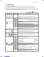
Page 48: ... error Heat exchanger sensor TA error Discharge temp sensor TD error Temp sensor TE TS error Outside air temp sensor TO error Suction temp sensor TS error Heat sink temp sensor TH error Miss mounting of temp sensor TE TS Indoor EEPROM error Outdoor EEPROM error Compressor break down Outdoor compressor system error Compressor lock Outdoor unit current detection circuit error Duplicated header indoo...

Page 49: ...rature TA Indoor heat exchanger Coil temperature TCJ Indoor heat exchanger Coil temperature TC Indoor fan revolution frequency Indoor fan calculated operation time Filter sign time Indoor discharge temperature 1 4 way only Unit C C C C rpm 100h 1h C Outdoor unit data CODE No 60 61 62 63 6A F1 Data name Outdoor heat exchanger Coil temperature TE Outside temperature TO Compressor discharge temperatu...

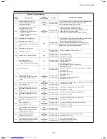
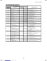
Page 50: ... Outdoor Heat sink overheat error Gas leak detection or 4 way valve system error 1E P03 ALT Outdoor unit Discharge temp error Outdoor Error was detected by discharge temp release control 21 P04 ALT Outdoor unit High pressure SW system error Outdoor High pressure protection switch operated AF P05 ALT Power supply error Outdoor Power supply voltage error 1C P07 ALT Outdoor unit Heat sink overheat er...

Page 51: ...ed 96 L03 SIM Duplicated indoor master units Indoor There are multiple master units in a group 99 L07 SIM There is group cable in individual indoor unit Indoor When even one group connection indoor unit exists in individual indoor unit 99 L08 SIM Unset indoor group address Indoor Indoor address group was unset 46 L09 SIM Unset indoor capacity Indoor Capacity of indoor unit was unset 66 L30 SIM Out...

Page 52: ...oor unit normally operates Check P C board Indoor receiving Outdoor sending 1 Check whether remote controller connection Group Individual was changed or not after power supply turned on Finish of group construction Address check If group construction and address are not normal when the power has been turned on the mode automatically shifts to address setup mode Resetting of address 1 Set indoor ca...

Page 53: ...ected Displayed when error is detected Displayed when error is detected Displayed when error is detected Displayed when error is detected Displayed when error is detected Displayed when error is detected Displayed when error is detected Displayed when error is detected Displayed when error is detected Displayed when error is detected Judgmentandmeasures 1 Check discharge temp sensor TD 2 Check out...

Page 54: ...heck PMV Pulse Motor Valve 3 Check discharge temp sensor TD 1 Check service valves are fully opened Gas side Liquid side 2 Check outdoor fan operation 3 Check motor error of outdoor fan 4 Check clogging of outdoor PMV 5 Check clogging of heat exchanger in indoor outdoor units 6 Short circuit of suction discharge air in outdoor unit 7 Check outdoor P C board error 8 Check fan system error Cause of ...

Page 55: ...ditioner Stop If center exists operation continues If center exists operation continues Stop Sub unit continues operation Continues By remote controller Continuation Stop According to each case Condition Displayed when error is detected Displayed when error is detected Displayed when error is detected Displayed when error is detected Displayed when error is detected Displayed when error is detecte...

Page 56: ... wiring of terminal block Does the case thermo operate Is the compressor abnormally heated Check and correct charged refrigerant amount YES YES YES NO NO NO NO YES E04 Indoor Outdoor communication error FILE NO SVM 18042 1 F04 F06 Discharge temp sensor TD error Heat exchanger temp sensor TE error Is CN61 connection correct Is resistance value of TE sensor correct Correct connector Sensor error Rep...

Page 57: ...e of TO sensor correct YES NO Correct connector Sensor error Replace Check outdoor P C board Defect Replace Is CN64 connection correct Is resistance value of TS sensor correct YES NO Check outdoor P C board Defect Replace Check outdoor P C board Defect Replace Correct connector Sensor error Replace Correct connector Sensor error Replace Correct sensor mounting Is mounting status of TE and TS senso...

Page 58: ...ead P C board side Compressor side Reactor lead Power supply lead YES YES YES NO NO NO Check wire connection and correct it Correct power supply line Is compressor under correct condition Is there refrigerant stagnation Does PMV correctly operate Is power supply voltage correct 50 Hz AC 198 to 264 V 60 Hz AC 198 to 242 V Is wire connection correct Compressor lead P C board side Compressor side Rea...

Page 59: ...of TD sensor correct Is there gas leak Is there refrigerant shortage YES NO NO YES NO NO YES YES Discharge temp error P03 Is PMV under correct condition Remove and improve the cause of overload 59 FILE NO SVM 18042 1 P05 Power supply error P07 Heat sink overheat error Confirm power supply etc Check outdoor P C board Defect Replace YES NO Is the power supply voltage is lower than or over the range ...

Page 60: ...r CN603 60 FILE NO SVM 18042 1 4 way valve inverse error P19 Is operation of 4 way valve correct Check pipe temp and etc in cooling heating operation NO Are temperature sensors correct TE sensor GM30 40 CN61 TS sensor GM30 40 CN64 NO YES YES NO YES Are resistance value of indoor TC and TCJ sensors correct Check and replace of PMV Replace TE sensor Replace TS sensor Replace coil of 4 way valve Repl...

Page 61: ...sistance values of indoor TC and TCJ sensors correct Replace sensor Check the same items as P22 error Check overcharge of refrigerant clogging of cycle broken pipe abnormal overload etc Defect Correct defective position Check overcharge of refrigerant clogging of cycle broken pipe abnormal overload etc Defect Correct defective position Eliminate interfering element Eliminate interfering element He...

Page 62: ... black lead wire 12 to 35Ω Between black and red lead wire 12 to 35Ω YES NO 62 P26 P29 Short circuit of compressor driving elements No code Position detection circuit error Other Compressor disorder due to sudden change of load etc Although the display of outdoor LED outputs the unit automatically restarts and error is not determined A code may appear when an open phase of compressor coming out of...

Page 63: ... 3 594 2 236 2 343 2 454 1 540 1 623 1 709 1 082 1 146 1 213 0 7740 0 8237 0 8761 0 5634 0 6023 0 6434 Temperature C 0 10 20 25 30 40 50 60 70 80 90 100 Resistance value kΩ Ω Ω Ω Ω Minimum value Standard value Maximum value 150 5 161 3 172 7 92 76 99 05 105 6 58 61 62 36 66 26 47 01 49 93 52 97 37 93 40 22 42 59 25 12 26 55 28 03 17 00 17 92 18 86 11 74 12 34 12 95 8 269 8 668 9 074 5 925 6 195 6 ...

Page 64: ...ue of each winding by using the tester Position Resistance value Red White White Black Black Red at 20 C Red White Black 3 Fan motor Model WDF 340 A43 1 Measure the resistance value of each winding by using the tester Position Resistance value Red White White Black Black Red at 20 C Red White Black 4 4 way valve coil Cooling heating switching Model SQA2522G 000352 Measure the resistance value of e...

Page 65: ... TEST FILTER L L RESET TEMP CL FAN SAVE A A SWING FIX VENT MODE ON OFF UNIT LOUVER T Contents The error contents in the past can be called Procedure 1 Push SET TEST buttons simultaneously for 4 seconds or more to call the service check mode Service Check goes on the CODE No is displayed and then the content of the latest alarm is displayed The number and error contents of the indoor unit in which ...

Page 66: ...ntroller Remote controller operation is available Approx 50 seconds after power ON Regular communication between indoor units Every 30 seconds Master Follower When the above status changes immediately communicates Repetition ë The unit without power feed waits entirely Waiting status is released by system start ë Reboot when power is fed on the way 3 minutes elapse O N l a m r o n t o N YES Automa...

Page 67: ... connected to each indoor unit respectively in the group operation even if multiple refrigerant lines are provided the automatic address setup completes with power ON of the outdoor unit The operation of the remote controller is not accepted while automatic address works Approx 4 to 5 minutes When the following addresses are not stored in the neutral memory IC503 on the indoor P C board a test run...

Page 68: ...Except errors and response to demand of service data Header unit Representative unit This unit communicates with the indoor unit follower which serial communicates with the outdoor units and sends receives signal Command from compressor to from the outdoor units as the representative of the cycle control in the indoor units of the identical line ad dress within the minimum unit which configures on...

Page 69: ...er Without identical line address indoor outdoor serial and then finally controls the outdoor compressor matching with its own thermo status The header unit sends this command information to the follower unit Follower unit The follower unit receives the indoor unit data from the header With identical line address indoor outdoor serial and then performs the thermo operation synchronized with the he...

Page 70: ...upply Automatic completion 2 Group operation Multiple outdoor units Multiple indoor units with serial communication only without twin Only turning on source power supply Automatic completion 1 Single 2 1 Sub Header 1 1 Sub Header 3 1 Master Header 8 1 Sub Header 1 1 Individual Master Header Max 8 units 70 FILE NO SVM 18042 ...

Page 71: ...side Indoor Outdoor connecting wires Outdoor side Example of 2 lines cabling Real line Cabling Broken line Refrigerant pipe For the above example perform setting by connecting singly the wired remote controller without remote controller inter unit cable Group address Individual 0000 Master unit 0001 Sub unit 0002 In case of group control Outdoor Indoor A B A B 1 2 3 Indoor A B 1 2 3 Indoor A B 1 2...

Page 72: ...SET button OK when display goes on 11 Push TEST button Setup completes The status returns to the usual stop status 10 5 Confirmation of Indoor Unit No Position 1 To know the indoor unit addresses though position of the indoor unit body is recognized In case of individual operation Wired remote controller indoor unit 1 1 Follow to the procedure during operation Procedure 1 Push ON OFF button if the...

Page 73: ... units Repair the defective position or apply the rust resisting paint if necessary If an indoor unit operates for approx 8 hours or more per day usually it is necessary to clean the indoor outdoor units once three months at least These cleaning and maintenance should be carried out by a qualified dealer Although the customer has to pay the charge for the maintenance the life of the unit can be pr...

Page 74: ...the refrigerant to the outdoor unit For the refrigerant recovery work during reinstallation of repair work be sure to use the refrigerant recovery unit Recovery of refrigerant to the outdoor unit is unavailable otherwise a serious accident such as explosion or injury may be caused 11 HOW TO EXCHANGE COMPRESSOR 11 1 Exchanging Procedure of Compressor Outline 11 2 Exchange of Compressor For exchange...

Page 75: ...r taking off screws remove the upper cabinet pulling it upward 2 Attachment 1 Attach the waterproof cover CAUTION Be sure to attach a waterproof cover If it is not attached there is a possibility that water enters inside of the outdoor unit 2 Attach the upper cabinet ST1T Ø4 10L 5 pcs Hook the rear side of the upper cabinet to claw of the rear cabinet and then put it on the front cabinet 3 Perform...

Page 76: ...abinet and bottom slab ST1T Ø4 10 3 pcs 5 Remove the screw between front cabinet and motor base ST1T Ø4 10 2 pcs Left side of front panel is inserted into side cabinet left Remove by pulling the upper part 2 How to install 1 Insert front panel s hook into side cabinet left 2 Insert side cabinet left s hook into front cabinet s corner hole 3 Insert the removed screws to their positions Motor base F...

Page 77: ...e inverter for 1minute after power has been turned off because an electric shock may be caused 3 Perform 1 of 2 4 Take off screw between side cabinet right and inverter box wiring gate side ST1T Ø4 10 2 pcs 5 Take off screw between partition plate and inverter box ST1T Ø4 10 1 pc 6 Remove each lead wire type from holder of inverter upper part 7 Pull upper part of inverter Here please cut bundling ...

Page 78: ...nnector lkkb qflk ql ljmobpplo 3P Relay connector white Warning 1 Reactor 2P Relay connector white CN31 Outdoor fan 3P white Warning 1 CN72 4 directional valve 3P yellow Warning 1 CN73 PMV coil 6P white Warning 1 CN62 TD sensor 3P white CN64 TS sensor 3P white Warning 1 CN61 TE sensor 2P white Warning 1 CN63 TO sensor 2P white CN52 High pressure switch 2P white Warning 1 Warning 1 Please remove ho...

Page 79: ...Orange with inverter box metal plate Warning 1 Please remove housing part s lock before removing connectors 3 4 Remove inrter box from base P C board base by disengage P C board base s hook Hook1 2 3 4 and pull inverter box up Remove control board frame from PC board base Remove while heat sink is still attached to control board frame 5 Take off 5 screws that connect heat sink and control board fr...

Page 80: ...sened To tighten the flange nut turn counterclockwise 3 Remove the propeller fan 4 Disconnect the connector for fan motor from the inverter 5 Take off the fixing screws 3 pcs holding by hands so that the fan motor does not fall NOTE Tighten the flange nut with torque 4 9Nm 50kgf cm Remarks 1 Perform works of items 1 of 1 and 2 3 2 Take off fixed screws for the bottom plate ST1T Ø4 10L 2 pcs 3 Take...

Page 81: ...ssor terminals after replacement of the compressor be sure to caulk the Faston terminal without loosening Remarks 1 Perform works of items 1 of 1 and 2 3 5 2 Discharge refrigerant gas 3 Remove the partition plate ST1T Ø4 10L 3 pcs 4 Remove the terminal covers of the compressor and disconnect lead wires of the compressor and the compressor thermo assembly from the terminal 5 Take off the soundproof...

Page 82: ... 2 Remove the front cabinet and put it down so that fan guard side directs downward CAUTION Perform works on a corrugated cardboard cloth etc to prevent flaw on the product 3 Remove the hooking claws by pushing with minus screwdriver along with the arrow mark in the right figure and remove the fan guard 2 Attachment 1 Insert claws of the fan guard in the hole of the front cabinet Push the hooking ...

Page 83: ...13 EXPLODED VIEWS AND PARTS LIST 13 1 RAV GM301ATP E RAV GM301ATP TR 83 FILE NO SVM 18042 1 2 3 4 5 6 7 8 9 10 11 12 13 14 15 16 28 17 29 18 19 20 21 30 22 23 24 26 27 33 34 35 36 37 25 31 32 ...

Page 84: ...VALVE PACKED 6 35 DIA 1 1 17 43T46503 VALVE PACKED 9 52 DIA 1 1 18 43T43559 CONDENSER ASSEMBLY 1 1 20 43T21460 FAN MOTOR 1 1 21 43T20319 PROPELLER FAN 1 1 22 43T19364 FAN GUARD 1 1 23 43T19331 FIN GUARD 1 1 24 43T58309 REACTOR 1 1 25 43T60420 ASM COMP LEAD 1 1 26 43T63369 SWITCH PRESSURE 1 1 27 43T49327 CUSHION RUBBER 3 3 28 43T47403 BONNET 6 35 DIA 1 1 29 43T47404 BONNET 9 52 DIA 1 1 30 43T39346 ...

Page 85: ... Inverter assembly GM30 85 FILE NO SVM 18042 706 707 708 705 711 710 702 701 709 703 TO Sensor Ø6 TE Sensor Ø6 TS Sensor Ø6 TD Sensor Ø4 704 ...

Page 86: ...3 43T60384 TERMINAL 6P 1 1 704 43T60326 FUSE 1 1 705 43T50369 TEMPERATURE SENSOR 1 1 706 43T50336 TEMPERATURE SENSOR 1 1 707 43T50370 TEMPERATURE SENSOR 1 1 708 43T50371 TEMPERATURE SENSOR 1 1 709 43T62313 PC PLATE BASE 1 1 710 43T60463 FUSE 1 1 711 43T60425 FUSE HOLDER 1 1 RAV Ref No Parts No Description ...

Page 87: ...13 2 RAV GM301ATJP E 87 FILE NO SVM 18042 1 2 3 4 5 6 7 8 9 10 11 12 13 14 15 16 28 17 29 18 19 20 21 30 22 23 24 26 27 33 34 35 36 37 25 31 32 ...

Page 88: ...46435 VALVE PACKED 6 35 DIA 1 17 43T46503 VALVE PACKED 9 52 DIA 1 19 43T43587 CONDENSER ASSEMBLY 1 20 43T21460 FAN MOTOR 1 21 43T20319 PROPELLER FAN 1 22 43T19364 FAN GUARD 1 23 43T19331 FIN GUARD 1 24 43T58309 REACTOR 1 25 43T60420 ASM COMP LEAD 1 26 43T63369 SWITCH PRESSURE 1 27 43T49327 CUSHION RUBBER 3 28 43T47403 BONNET 6 35 DIA 1 29 43T47404 BONNET 9 52 DIA 1 30 43T39346 NUT FLANGE 1 31 4308...

Page 89: ... Inverter assembly GM30 89 FILE NO SVM 18042 706 707 708 705 711 710 702 701 709 703 TO Sensor Ø6 TE Sensor Ø6 TS Sensor Ø6 TD Sensor Ø4 704 ...

Page 90: ... 1 703 43T60384 TERMINAL 6P 1 704 43T60326 FUSE 1 705 43T50369 TEMPERATURE SENSOR 1 706 43T50336 TEMPERATURE SENSOR 1 707 43T50370 TEMPERATURE SENSOR 1 708 43T50371 TEMPERATURE SENSOR 1 709 43T62313 PC PLATE BASE 1 710 43T60463 FUSE 1 711 43T60425 FUSE HOLDER 1 Ref No Parts No Description ...

Page 91: ...13 3 RAV GM401ATP E RAV GM401ATP TR 91 FILE NO SVM 18042 1 2 3 4 5 6 7 8 9 10 11 12 13 14 15 16 28 17 29 18 19 20 21 30 22 33 24 25 26 27 36 35 34 23 31 32 ...

Page 92: ...VALVE PACKED 6 35 DIA 1 1 17 43T46461 VALVE PACKED 12 7 DIA 1 1 18 43T43561 CONDENSER ASSEMBLY 1 1 20 43T21460 FAN MOTOR 1 1 21 43T20319 PROPELLER FAN 1 1 22 43T19364 FAN GUARD 1 1 23 43T19331 FIN GUARD 1 1 24 43T58309 REACTOR 1 1 25 43T60420 ASM COMP LEAD 1 1 26 43T63369 SWITCH PRESSURE 1 1 27 43T49327 CUSHION RUBBER 3 3 28 43T47403 BONNET 6 35 DIA 1 1 29 43T47405 BONNET 12 7 DIA 1 1 30 43T39346 ...

Page 93: ... Inverter assembly GM40 93 FILE NO SVM 18042 706 707 708 705 711 710 702 701 709 703 TO Sensor Ø6 TE Sensor Ø6 TS Sensor Ø6 TD Sensor Ø4 704 ...

Page 94: ...3 43T60384 TERMINAL 6P 1 1 704 43T60326 FUSE 1 1 705 43T50369 TEMPERATURE SENSOR 1 1 706 43T50336 TEMPERATURE SENSOR 1 1 707 43T50370 TEMPERATURE SENSOR 1 1 708 43T50371 TEMPERATURE SENSOR 1 1 709 43T62313 PC PLATE BASE 1 1 710 43T60463 FUSE 1 1 711 43T60425 FUSE HOLDER 1 1 RAV Ref No Parts No Description ...

Page 95: ...13 4 RAV GM401ATJP E 95 FILE NO SVM 18042 1 2 3 4 5 6 7 8 9 10 11 12 13 14 15 16 28 17 29 18 19 20 21 30 22 33 24 25 26 27 36 35 34 23 31 32 ...

Page 96: ...V 1 1 16 43T46435 VALVE PACKED 6 35 DIA 1 1 17 43T46461 VALVE PACKED 12 7 DIA 1 1 18 43T43561 CONDENSER ASSEMBLY 1 1 20 43T21460 FAN MOTOR 1 1 21 43T20319 PROPELLER FAN 1 1 22 43T19364 FAN GUARD 1 1 23 43T19331 FIN GUARD 1 1 24 43T58309 REACTOR 1 1 25 43T60420 ASM COMP LEAD 1 1 26 43T63369 SWITCH PRESSURE 1 1 27 43T49327 CUSHION RUBBER 3 3 28 43T47403 BONNET 6 35 DIA 1 1 29 43T47405 BONNET 12 7 DI...

Page 97: ... Inverter assembly GM40 97 FILE NO SVM 18042 706 707 708 705 711 710 702 701 709 703 TO Sensor Ø6 TE Sensor Ø6 TS Sensor Ø6 TD Sensor Ø4 704 ...

Page 98: ... 1 703 43T60384 TERMINAL 6P 1 704 43T60326 FUSE 1 705 43T50369 TEMPERATURE SENSOR 1 706 43T50336 TEMPERATURE SENSOR 1 707 43T50370 TEMPERATURE SENSOR 1 708 43T50371 TEMPERATURE SENSOR 1 709 43T62313 PC PLATE BASE 1 710 43T60463 FUSE 1 711 43T60425 FUSE HOLDER 1 Ref No Parts No Description ...

Page 99: ...ffocation from leakage of R32 is almost non existent If a conditioner system is to be installed in a small room select a suitable model and installation procedure so that if the refrigerant accidentally leaks out its concentration does not reach the limit and in the event of an emergency measures can be made before injury can occur In a room where the concentration may exceed the limit create an o...

Page 100: ...144 9 MOO 5 BANGKADI INDUSTRIAL PARK TIVANON ROAD TAMBOL BANGKADI AMPHUR MUANG PATHUMTHANI 12000 THAILAND ...

Reviews: