Toshiba RAV-GM 1101UT-E Service Manual Download Page 124

– 124 –

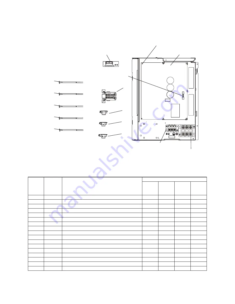
14-2. Inverter Assembly

703

704

705

706

707

PC BOARD A

SS

Y, MCC-1646

702

HOLDER, 

S

EN

S

OR(TO)

70

9

710

HOLDER, 

S

EN

S

OR(TE)

716

717

S

PACER, COLLAR

S

PACER, BU

S

H

701

714

TERMINAL BLACK,3P 20A

715

TERMINAL BLACK,3P 60A

713

711

HOLDER, 

S

EN

S

OR(TD)

712

HOLDER, 

S

EN

S

OR(T

S

)

S

EN

S

OR, TD

S

EN

S

OR, TL

S

EN

S

OR, TE

S

EN

S

OR, TO

S

EN

S

OR, T

S

FU

S

E(10A)

PC BOARD A

SS

Y, MCC-1705

70

8

Location

No.

Part No.

Q’ty/Set      RAV-GP

701

702

70

3

704

705

706

707

708

709

710

711

712

71

3

714

715

716

717

4

3

16V659

4

3

16V550

4

3

150

3

51

4

3

150

3

55

4

3

150

3

59

4

3

150

3

69

4

3

150

3

70

4

3

150

3

5

3

4

3

16

3

055

4

3

F6

33

25

4

3

F6

33

21

4

3

F6

33

22

4

3

160589

4

3

160607

4

3

160609

4

3

16

3

059

4

3

16

3

066

PC BOARD ASSY, MCC-1705

PC BOARD ASSY, MCC-1646, DS

SENSOR, TD

SENSOR, TL

SENSOR, TE

SENSOR, TO

SENSOR, TS

SENSOR, TS

HOLDER, SENSOR (TO)

HOLDER, SENSOR (TE)

HOLDER, SENSOR (TD)

HOLDER, SENSOR (TS)

FUSE, 10A

TERMINAL BLOCK, 

3

P, 20A

TERMINAL BLOCK, 

3

P, 60A

SPACER, BUSH

SPACER, COLLAR

801AT-E

801AT-TR 801ATJ-E

1101AT-E
1401AT-E

1101AT-TR
1401AT-TR

1101ATJ-E
1401ATJ-E

1

1

1

1

1

1

1

1

1

1

1

1

1

1

1

1

1

1

1

1

1

1

1

1

1

1

1

1

1

1

1

1

1

1

1

1

1

1

1

1

1

1

1

1

1

1

1

1

1

1

1

1

1

1

1

1

1

1

1

1

Description

Summary of Contents for RAV-GM 1101UT-E

Page 1: ...FILE No A10 1809 SERVICE MANUAL AIR CONDITIONER SPLIT TYPE OUTDOOR UNIT SUPER DIGITAL INVERTER RAV GP801AT E RAV GP801AT TR RAV GP1101AT E RAV GP1101AT TR RAV GP1401AT E RAV GP1401AT TR RAV GP801ATJ E RAV GP1101ATJ E RAV GP1401ATJ E ...

Page 2: ...TRICAL PARTS 38 5 1 Outdoor Unit 38 6 REFRIGERANT R32 39 6 1 Safety During Installation Servicing 39 6 2 Refrigerant Piping Installation 39 6 2 1 Piping Materials and Joints Used 39 6 2 2 Processing of Piping Materials 40 6 3 Tools 43 6 3 1 Required Tools 43 6 4 Recharging of Refrigerant 43 6 5 Brazing of Pipes 44 6 5 1 Materials for Brazing 44 6 5 2 Flux 44 6 5 3 Brazing 45 6 6 Instructions for R...

Page 3: ...or Each Check Code Outdoor Unit 69 9 SETUP AT LOCAL SITE AND OTHERS 80 9 1 Calling of Check code History 80 9 2 Outdoor Unit 82 10 ADDRESS SETUP 91 10 1 Address Setup Procedure 91 10 2 Address Setup Group Control 92 10 2 1 System Configuration 93 10 2 2 Automatic Address Example from Unset Address No miswiring 94 10 3 Remote Controller Wiring 94 10 4 Address Setup Manual setting from remote contro...

Page 4: ... has been instructed in such matters by an individual or individuals who have been trained and is thus thoroughly acquainted with the knowledge related to this work The qualified installer who is allowed to work at heights has been trained in matters relating to working at heights with the air conditioners made by Toshiba Carrier Corporation or alternatively he or she has been instructed in such m...

Page 5: ... provide protection for electricians Insulating shoes Clothing to provide protection from electric shock Helmets for use in industry Shoes with additional protective toe cap Gloves to provide protection for electricians Indication DANGER WARNING CAUTION Explanation Indicates contents assumed that an imminent danger causing a death or serious injury of the repair engineers and the third parties whe...

Page 6: ...get burned when removing this panel CAUTION Do not touch the aluminum fins of the unit Doing so may result in injury CAUTION BURST HAZARD Open the service valves before the operation otherwise there might be the burst Description WARNING ELECTRICAL SHOCK HAZARD Disconnect all remote electric power supplies before servicing WARNING Moving parts Do not operate unit with grille removed Stop the unit ...

Page 7: ...n electric shocks through contact with the interior parts Only a qualified installer 1 or qualified service person 1 is allowed to remove the intake grille of the indoor unit or service panel of the outdoor unit and do the work required Bef Do not turn ON the circuit breaker under the condition of removing a cabinet a panel etc Otherwise it leads to an electric shock with a high voltage resulting ...

Page 8: ...thing and then proceed Do not climb onto or place objects on top of the outdoor unit You may fall or the objects may fall off of the outdoor unit and result in injury When transporting the air conditioner wear shoes with additional protective toe caps When transporting the air conditioner do not take hold of the bands around the packing carton You may injure yourself if the bands should break This...

Page 9: ... out repairs it becomes absolutely necessary to check out the electrical parts with the electrical parts box cover of one or more of the indoor units and the service panel of the outdoor unit removed in order to find out exactly where the trouble lies place Keep out signs around the work site before proceeding Third party individuals may enter the work site and receive electric shocks if this warn...

Page 10: ...e refrigerant abnormal high pressure generates in the refrigerating cycle resulted in cause of injury due to breakage After the installation work confirm that refrigerant gas does not leak If refrigerant gas leaks into the room and flows near a fire source such as a cooking range it may generate noxious gases causing a fire Never recover the refrigerant into the outdoor unit When the equipment is ...

Page 11: ...ly after the air conditioner has been shut down set the circuit breaker to the OFF position and then wait at least 10 minutes before opening the service panel If you fail to heed this warning you will run the risk of burning yourself because the compressor pipes and other parts will be very hot to the touch In addition before proceeding with the repair work wear the kind of insulated heat resistan...

Page 12: ...n raising the pressure inside the refrigeration cycle to an abnormally high level and possibly resulting in reputing injury etc When removing the welding parts of suction and discharge pipe for the compressor remove them at the place ventilated well after recovering the refrigerant Improper recovering may cause the spurt of the refrigerant and the refrigeration oil causing an injury Do not vent ga...

Page 13: ...ossibly resulting in reputing injury etc 1 Refer to the Definition of Qualified Installer or Qualified Service Person Declaration of Conformity Manufacturer TOSHIBA CARRIER CORPORATION 336 Tadehara Fuji shi Shizuoka ken 416 8521 JAPAN TCF holder TOSHIBA CARRIER EUROPE S A S Route de Thil 01120 Montluel FRANCE Hereby declares that the machinery described below Generic Denomination Air Conditioner M...

Page 14: ...e to check for leakage refrigerant or residual refrigerant If the leakage refrigerant comes into contact with fire a poisonous gas may occur or it may cause a fire Keep adequate ventilation during the work 4 When refrigerant gas leaks during work execute ventilation If the leakage refrigerant comes into contact with a fire a poisonous gas may occur or it may cause a fire 5 In places where installi...

Page 15: ...igerant changes and then characteristics of the air conditioner change 3 Pipe Materials For the refrigerant pipes copper pipe and joints are mainly used It is necessary to select the most appropriate pipes to conform to the standard Use clean material in which impurities adhere inside of pipe or joint to a minimum 1 Copper pipe Be sure to select the pipes with copper thickness in the table below s...

Page 16: ...frigerant type may cause not only damage of the equipments but also a fire etc R410A tools available Partly unavailable R410A tools unavailable No Installation service tools Tools Equipment specification 1 Flare tool Clutch type Pipe flaring Use Applicability to R32 air conditioner or not Applicability to R22 air conditioner or not 5 Charge hose High voltage 3 Torque wrench Tightening of flare nut...

Page 17: ...tdoor lower m Outdoor high m Outer dimension Max total length m 50 3 30 30 Propeller fan 53 60 15 9 9 5 15 9 9 5 46 48 63 65 75 3 30 30 Propeller fan 116 100 100 15 9 9 5 15 9 9 5 49 50 66 67 75 3 30 30 Propeller fan 116 100 100 15 9 9 5 15 9 9 5 50 51 67 68 Fan Min length m Sound pressure level H M M L L dB A Sound power level H M M L L dB A Fan Power consumption kW Power factor EER SEER Energy e...

Page 18: ...nch Gas side mm Liquid side mm Pipe branch indoor unit Gas side mm Liquid side mm Standard air flow high Fan unit m3 min Motor W Height difference Outdoor lower m Outdoor high m Outer dimension Max total length m 75 3 30 30 Propeller fan 116 100 100 15 9 9 5 12 7 6 4 49 50 66 67 75 3 30 30 Propeller fan 116 100 100 15 9 9 5 15 9 9 5 50 51 67 68 Fan Min length m Sound pressure level H M M L L dB A ...

Page 19: ...side mm Pipe branch indoor unit Gas side mm Liquid side mm Standard air flow high Fan unit m3 min Motor W Height difference Outdoor lower m Outdoor high m Outer dimension Max total length m 50 3 30 30 Propeller fan 53 60 15 9 9 5 15 9 9 5 46 48 63 65 75 3 30 30 Propeller fan 116 100 100 15 9 9 5 15 9 9 5 49 50 66 67 75 3 30 30 Propeller fan 116 100 100 15 9 9 5 15 9 9 5 50 51 67 68 Fan Min length ...

Page 20: ... side mm Pipe branch indoor unit Gas side mm Liquid side mm Standard air flow high Fan unit m3 min Motor W Height difference Outdoor lower m Outdoor high m Outer dimension Max total length m 75 3 30 30 Propeller fan 116 100 100 15 9 9 5 12 7 6 4 49 50 66 67 75 3 30 30 Propeller fan 116 100 100 15 9 9 5 15 9 9 5 50 51 67 68 Fan Min length m Sound pressure level H M M L L dB A Sound power level H M ...

Page 21: ...as side mm Liquid side mm Pipe branch indoor unit Gas side mm Liquid side mm Standard air flow high Fan unit m3 min Motor W Height difference Outdoor lower m Outdoor high m Outer dimension Max total length m 50 3 30 30 Propeller fan 53 60 15 9 9 5 15 9 9 5 46 48 63 65 75 3 30 30 Propeller fan 116 100 100 15 9 9 5 12 7 6 4 49 50 66 67 Fan Min length m Sound pressure level H M M L L dB A Sound power...

Page 22: ...side mm Pipe branch indoor unit Gas side mm Liquid side mm Standard air flow high Fan unit m3 min Motor W Height difference Outdoor lower m Outdoor high m Outer dimension Max total length m 50 3 30 30 Propeller fan 53 60 15 9 9 5 15 9 9 5 46 48 63 65 50 3 30 30 Propeller fan 53 60 15 9 9 5 12 7 6 4 46 48 63 65 Fan Min length m Sound pressure level H M M L L dB A Sound power level H M M L L dB A Fa...

Page 23: ...iquid side mm Pipe branch indoor unit Gas side mm Liquid side mm Standard air flow high Fan unit m3 min Motor W Height difference Outdoor lower m Outdoor high m Outer dimension Max total length m 50 3 30 30 Propeller fan 53 60 15 9 9 5 15 9 9 5 46 48 63 65 75 3 30 30 Propeller fan 116 100 100 15 9 9 5 15 9 9 5 49 50 66 67 75 3 30 30 Propeller fan 116 100 100 15 9 9 5 15 9 9 5 50 51 67 68 Fan Min l...

Page 24: ...quid side mm Pipe branch indoor unit Gas side mm Liquid side mm Standard air flow high Fan unit m3 min Motor W Height difference Outdoor lower m Outdoor high m Outer dimension Max total length m 75 3 30 30 Propeller fan 116 100 100 15 9 9 5 12 7 6 4 49 50 66 67 75 3 30 30 Propeller fan 116 100 100 15 9 9 5 15 9 9 5 50 51 67 68 Fan Min length m Sound pressure level H M M L L dB A Sound power level ...

Page 25: ...iquid side mm Pipe branch indoor unit Gas side mm Liquid side mm Standard air flow high Fan unit m3 min Motor W Height difference Outdoor lower m Outdoor high m Outer dimension Max total length m 50 3 30 30 Propeller fan 53 60 15 9 9 5 15 9 9 5 46 48 63 65 75 3 30 30 Propeller fan 116 100 100 15 9 9 5 15 9 9 5 49 50 66 67 75 3 30 30 Propeller fan 116 100 100 15 9 9 5 15 9 9 5 50 51 67 68 Fan Min l...

Page 26: ...it Pipe branch Gas side mm Liquid side mm Pipe branch indoor unit Gas side mm Liquid side mm Standard air flow high Fan unit m3 min Motor W Height difference Outdoor lower m Outdoor high m Outer dimension Max total length m 50 3 30 30 Propeller fan 53 60 15 9 9 5 12 7 6 4 46 48 63 65 75 3 30 30 Propeller fan 116 100 100 15 9 9 5 12 7 6 4 49 50 66 67 75 3 30 30 Propeller fan 116 100 100 15 9 9 5 15...

Page 27: ... Gas side Liquid side Cooling Heating Cooling Heating Heat exchanger Finned tube Refrigerant control Pulse motor valve Pipe 75 3 30 30 1550 1010 370 75 3 30 30 1550 1010 370 50 3 30 30 1050 1010 370 Max m Min m Height difference Outdoor lower Outdoor high m m Appearance Silky shade Muncel 1Y8 5 0 5 Type Motor Compressor kW Pole Hermetic compressor 2 00 6 1 9 3 75 4 3 1 3 75 4 3 1 Fan Standard air ...

Page 28: ...70 60 50 40 30 20 Current A Outdoor temperature C 27 24 21 18 15 12 9 6 3 0 3 6 9 12 GP801 Conditions Indoor DB20 C Indoor air flow High GP1101 1401 110 105 100 95 90 85 80 75 70 65 60 55 50 45 40 Current A Outdoor temperature C 32 34 36 38 40 42 44 46 48 50 52 GP1101 1401 Conditions Indoor DB27 C WB19 C Indoor air flow High 110 100 90 80 70 60 50 40 30 20 Current A Outdoor temperature C 27 24 21 ...

Page 29: ...ting Conditions Indoor DB20 C Outdoor DB 7 C WB6 C Indoor air flow High Pipe length 7 5m 20 18 16 14 12 10 8 6 4 2 0 Current A Compressor speed rps 0 10 20 30 40 50 60 70 80 90 100 Conditions Indoor DB27 C WB19 C Outdoor DB35 C Indoor air flow High Pipe length 7 5m 20 18 16 14 12 10 8 6 4 2 0 Current A Compressor speed rps 0 10 20 30 40 50 60 70 80 90 100 110 Cooling Heating Conditions Indoor DB20...

Page 30: ... 30 2 CONSTRUCTION VIEWS EXTERNAL VIEWS 2 1 RAV GP801AT ...

Page 31: ... 31 2 2 RAV GP1101AT GP1401AT ...

Page 32: ... Simultaneous Twin Joint pipe Inner diameter Ø28 6 1 pc Outer diameter Ø25 4 Inner diameter Ø C Inner diameter Ø D Inner diameter Ø D A B 24 22 54 A B C D 74 37 25 4 15 9 35 Gas side Liquid side 18 12 7 9 5 Model RBC TWP101E Q ty 1 1 ...

Page 33: ...xchanger TS sensor High pressure switch Automatic restoration OFF 4 15Mpa ON 3 2MPa 4 way valve TD sensor Compressor Accumulator 1500cc Muffler Ø25 X L180 Muffler Ø25 X L210 Strainer Ø25 4 Cooling Low pressure Heating High pressure Gas pipe Ø15 9 Packed valve Liquid pipe Ø9 5 Packed valve Strainer Ø12 7 Distributor TE sensor Fan M ...

Page 34: ...toration OFF 4 15Mpa ON 3 2MPa 4 way valve TD sensor Compressor Accumulator 2500cc Muffler Ø25 L180 Muffler Ø25 L210 Strainer Ø25 4 Cooling Low pressure Heating High pressure Gas pipe Ø15 9 Packed valve Liquid pipe Ø9 5 Packed valve Strainer Ø12 7 Liquid tank 500cc Distributor TE sensor Fan M Cooling High pressure Heating Low pressure Check joint ...

Page 35: ... 24 4 34 2 30 0 33 0 44 4 26 4 78 6 HIGH HIGH LOW HIGH LOW HIGH 27 19 32 24 18 15 5 20 30 15 35 52 15 7 6 24 18 27 Pressure Pipe surface temperature C Compressor drive revolution frequency rps indoor fan Indoor outdoor temp condition Mpa kg cm2g Discharge suction indoor heat exchanger Outdoor heat exchanger Pd Ps Pd Ps TS TD TC TL TE indoor outdoor 2 7 3 6 1 9 2 5 3 6 1 6 1 0 1 4 0 7 0 7 1 1 0 2 c...

Page 36: ... 36 4 WIRING DIAGRAM 4 1 RAV GP801AT 220 240V 50Hz P 3 3 Fuse 25A 250V Fuse 10A 250V ...

Page 37: ... 37 4 2 RAV GP1101AT GP1401AT 220 240V 50Hz P 3 3 3 Fuse 25A 250V Fuse 10A 250V ...

Page 38: ...5 C 10mH 20A 10kΩ at 25 C 1 905kΩ at 120 C 10kΩ at 25 C 10kΩ at 25 C 1 905kΩ at 120 C 25A 250V 3 15A 250V 10A 250V 20A 250V No Parts name Type Specifications 1 2 3 4 5 6 7 8 9 10 11 12 13 14 15 16 17 18 Compressor Outdoor fan motor 4 way valve coil PMV coil High pressure switch Compressor thermostat Reactor P C board P C board LED display Outdoor temp sensor TO sensor Discharge temp sensor TD sens...

Page 39: ...ation cycle may become abnormally high so that a rupture or personal injury may be caused 5 After completion of installation work check to make sure that there is no refrigeration gas leakage If the refrigerant gas leaks into the room coming into contact with fire in the fan driven heater space heater etc a poisonous gas may occur 6 When an air conditioning system charged with a large volume of re...

Page 40: ...nimum thicknesses of socket joints Nominal diameter 1 4 3 8 1 2 5 8 Reference outer diameter of copper pipe jointed mm 6 4 9 5 12 7 15 9 Minimum joint thickness mm 0 50 0 60 0 70 0 80 6 2 2 Processing of Piping Materials When performing the refrigerant piping installation care should be taken to ensure that water or dust does not enter the pipe interior that no other oil other than lubricating oil...

Page 41: ...ness mm 0 8 0 8 0 8 1 0 1 0 Dimension mm A B C D 9 1 9 2 6 5 13 13 0 13 5 9 7 20 16 2 16 0 12 9 20 19 4 19 0 16 0 23 23 3 24 0 19 2 34 Flare nut width mm 17 22 24 27 36 Nominal diameter 1 4 3 8 1 2 5 8 3 4 Outer diameter mm 6 4 9 5 12 7 15 9 19 1 Thickness mm 0 8 0 8 0 8 1 0 1 2 Dimension mm A B C D 9 1 9 2 6 5 13 13 2 13 5 9 7 20 16 6 16 0 12 9 23 19 7 19 0 16 0 25 24 0 19 2 28 Flare nut width mm...

Page 42: ...es designated by manufacturers Table 6 2 6 shows reference values NOTE When applying oil to the flare surface be sure to use oil designated by the manufacturer If any other oil is used the lubricating oils may deteriorate and cause the compressor to burn out 43 to 45 45 to 46 A B C D Fig 6 2 2 Relations between flare nut and flare seal surface Table 6 2 6 Tightening torque of flare for R410A or R3...

Page 43: ...o 2 minutes and ensure that the compound gauge s pointer does not return Set the refrigerant cylinder to the electronic balance connect the connecting hose to the cylinder and the connecting port of the electronic balance and charge liquid refrigerant INDOOR unit Liquid side Refrigerant cylinder With siphon pipe Check valve Gas side Open Close valve for charging Electronic balance for refrigerant ...

Page 44: ...opper alloy and is relatively expensive though it excels in solderability 2 Phosphor bronze brazing filler Phosphor bronze brazing filler is generally used to join copper or copper alloy 3 Low temperature brazing filler Low temperature brazing filler is generally called solder and is an alloy of tin and lead Since it is weak in adhesive strength do not use it for refrigerant pipes 1 Phosphor bronz...

Page 45: ... cylinder Nitrogen gas Rubber plug Fig 6 5 1 Prevention of oxidation during brazing 1 Do not enter flux into the refrigeration cycle 2 When chlorine contained in the flux remains within the pipe the lubricating oil deteriorates Therefore use a flux which does not contain chlorine 3 When adding water to the flux use water which does not contain chlorine e g distilled water or ion exchange water 4 R...

Page 46: ...opper green rust generated 6 Check the oil when the existing air conditioner was removed after refrigerant had been recovered In this case if the oil is judged as clearly different compared with normal oil The refrigerator oil is copper rust green There is possibility that moisture is mixed with the oil and rust generates inside of the pipe There is discolored oil a large quantity of the remains o...

Page 47: ...s or longer recover the refrigerant Refer to 13 Refrigerant recovery For cleaning the pipes and recovering oil Refrigerant recovery Pump down method Connect the indoor outdoor units to the existing pipe Use a flare nut attacheindoor outdoor units Do not existing pipe Re machine the flare machining size to size for R32 Airtight test Vacuum dry Refrigerant charge Gas leak check Was largely discolore...

Page 48: ...pressure capacity 6 6 7 Recovering Refrigerant Use the refrigerant recovery equipment to recover the refrigerant 6 7 Charging additional refrigerant Amount of additional refrigerant shall be restricted by the following explanation to ensure the reliability Miss charging leads to the abnormal high pressure in the refrigerant cycle causing a rupture an injury and a compressor malfunction 6 7 1 Assum...

Page 49: ... compressor body shall be employed to accelerate this process When oil is drained from a system it shall be carried out safely 6 8 2 Decommissioning Before carrying out this procedure it is essential that the technician is completely familiar with the equipment and all its details Only a qualified installer 1 or qualified service person 1 is allowed to do this work It is recommended good practice ...

Page 50: ...use 250V 3 15A For Power supply circuit CN710 WHT Connector for Pulse motor valve CN701 WHT Connector for 4 way valve coil F01 Main Fuse 250V 25A Indoor outdoor communication LED D504 ORG outdoor indoor D502 GRN indoor outdoor F03 Fuse 250V 10A for lead wire between indoor and outdoor unit F02 Fuse 250V 3 15A for surge absorber P11 RED P12 WHT P13 GRY Lead wire for indoor unit P01 RED P02 WHT Lead...

Page 51: ...ion number of the compressor in the event that the discharge temperature is not reduced or in the event the discharge temperature increases rapidly during PMV control The cycle is stabilized by dividing compressor revolution number control into units up to 0 6 rps 2 When the detected discharge temperature is in a trouble zone compressor operation is stopped and then restarted after 2 minutes 30 se...

Page 52: ...x WE WD WB W9 W7 W5 W3 WE TL Revolution number HOLD WF tap 58 1tap 20sec 55 37 34 GP110 GP140 Less than 20 4rps 20 4rps or more and less than 52 rps 45 0rps or more 38 C TO 29 C TO 38 C 15 C TO 29 C 5 C TO 15 C 0 C TO 5 C 5 C TO 0 C TO 5 C To trouble Min W6 W5 W3 W2 W1 W1 OFF OFF Max WB WA W7 W5 W3 W2 W1 WB Min W8 W7 W5 W4 W3 W2 OFF OFF Max WF WE W9 W7 W5 W4 W1 WF Min WA W9 W7 W6 W4 W3 W2 W2 Max W...

Page 53: ...control 1 Heating operations of the outdoor fan are controlled by a TE sensor TO sensor and the compressor revolution number Control from a minimum W1 to a maximum is performed according to the table below 2 Operation is fixed for 3 minutes after start up by a maximum fan tap corresponding to the zones in the table below Thereafter fan control is performed using the temperature from the TE sensor ...

Page 54: ...r higher for 3 seconds or if the temperature is 7 C TE 12 C for 1 minute Furthermore the defrost operation will be terminated if defrosting operations have continued for 10 minutes even if TE sensor temperature is less than 7 C 3 After defrost operations have been reset the compressor restarts heating operations without stopping TE C 5 C 2 C 10 C 23 C 0 10 39 min 15 45 55 150 A zone D zone B zone ...

Page 55: ...from the right table 9 Over current protective control 1 Operation of the compressor is stopped when the over current protective circuit detects a trouble current 2 The compressor restarts after 2 minutes 30 seconds using 1 as a trouble count After restart the trouble count is cleared when operation continues for 6 minutes or more 3 A trouble is confirmed when the trouble count takes a value of 8 ...

Page 56: ...ned by TD and TO sensors When the TO sensor is defective a backup control is automatically performed by the TE sensor When TO sensor is defective make a determination using the LED display of the outdoor interface board 4 The power is turned off when TD is 30 C or more NOTE While heating and electrifying the winding wire electrifying sound may generate It is nor abnormal 70W Total power consumptio...

Page 57: ...erformed from remote controller Is not the control operation performed from outside remote side Is not automatic address being set up When the power is turned on at the first time or when indoor unit address setting is changed the operation cannot be performed for maximum approx 5 minutes after power ON Is not being carried out a test run by operation of the outdoor controller 5 LED for the inside...

Page 58: ...is turned on at the first time or when indoor unit address setting is changed the operation cannot be performed for maximum approx 5 minutes after power ON Is not being carried out a test run by operation of the outdoor controller 5 LED for the inside and outside communication does not flash Does not standby power saving operation control work LED does not flash when the inside and outside communi...

Page 59: ...r unit Receiving trouble Receiving unit Miswiring or wire connection trouble Sending trouble Communication stop between receiving unit and indoor unit Duplicated indoor unit No Setup trouble Duplicated header units of remote controller Communication trouble between CPUs on indoor unit P C board Wire connection trouble between indoor units Indoor power OFF Communication stop between indoor header a...

Page 60: ...le Temp sensor miswiring TE TS Indoor EEPROM trouble Outdoor EEPROM trouble Compressor break down Outdoor compressor system trouble 1 Compressor lock Current detection circuit trouble Power supply outdoor P C board trouble Case thermostat worked Compressor overheat outdoor wiring trouble PS pressure sensor trouble Outdoor unit low pressure protective operation low pressure system trouble Duplicate...

Page 61: ...on Timer Ready Simultaneous flash Operation Timer Ready Alternate flash Check code Cause of trouble occurrence During test run Disagreement of cool heat Automatic cool heat setting to automatic cool heat prohibited model or setting of heating to cooling only model ...

Page 62: ...mperature TD Compressor suction temperature TS Heat sink temperature THS Operation current 1 10 Outdoor heat exchanger Coil temperature TL Compressor operation frequency Outdoor fan revolution frequency Lower Outdoor fan revolution frequency Upper Compressor calculated operation time Unit C C C C C A C rps rpm rpm 100h 1 Push buttons simultaneously for 4 seconds to call the service monitor mode Th...

Page 63: ...utdoor unit Temp sensor TS trouble ALT Outdoor Open Short of suction temp sensor was detected F13 Outdoor unit Temp sensor TH trouble ALT Outdoor Open Short of heat sink temp sensor Board installed was detected F15 Outdoor unit Misconnection of temp sensor TE TS ALT Outdoor Misconnection of outdoor heat exchanger temp sensor and suction temp sensor was detected F07 Outdoor unit Temp sensor TL trou...

Page 64: ...temp TA was detected O F01 Indoor unit Heat exchanger sensor TCJ trouble ALT Indoor Open Short of heat exchanger TCJ was detected O F02 Indoor unit Heat exchanger sensor TC trouble ALT Indoor Open Short of heat exchanger TC was detected O There are multiple communication adapters Network adapter There are multiple communication adapters on remote controller communication line O O By unit with warn...

Page 65: ...d Displayed when trouble is detected Displayed when trouble is detected Displayed when trouble is detected Displayed when trouble is detected Displayed when trouble is detected Displayed when trouble is detected Displayed when trouble is detected Displayed when trouble is detected Displayed when trouble is detected Displayed when trouble is detected Displayed when trouble is detected Judgment and ...

Page 66: ...Ps sensor trouble Stop Displayed when trouble is detected 1 Check connection of Ps sensor connector 2 Check failure of Ps sensor 3 Check compressing power trouble of compressor 4 Check 4 way valve trouble 5 Check outdoor P C board trouble P07 Heat sink overheat trouble Heat sink temp sensor detected over specified temperature Stop Displayed when trouble is detected 1 Check screw tightening between...

Page 67: ...heck of outdoor fan operation 3 Check motor trouble of outdoor fan 4 Check clogging of outdoor PMV 5 Check clogging of heat exchanger in indoor outdoor units 6 Short circuit status of suction discharge air in outdoor unit 7 Check outdoor P C board trouble 8 Check fan system trouble Cause of air volume drop at indoor side 9 Check PMV opening status in indoor unit P03 Discharge temp trouble Discharg...

Page 68: ...nit wiring 2 Check remote controller 3 Check indoor power wiring 4 Check indoor P C board E02 Signal send trouble to indoor unit Detected by remote controller side Stop Automatic reset If center exists operation continues Displayed when trouble is detected Sending trouble of remote controller 1 Check sending circuit inside of remote controller Replace remote controller E09 There are multiple main ...

Page 69: ...off or rapidly flashing and that D805 is lit up If D800 to D804 are slowly flashing or D805 is flashing then push and hold down SW01 and SW02 at the same time for at least 5 seconds D800 to D804 will turn off or be rapidly flashing and D805 will change to flashing 2 Push and hold down SW01 for at least 5 seconds D804 will start slowly flashing 3 Push SW01 several times until reaching the LED indic...

Page 70: ...ace F07 Heat exchanger temp sensor TL trouble Is connection of CN604 correct Is resistance value of TL sensor correct YES NO Correct connector Replace TL sensor Check outdoor P C board Failure Replace F12 Suction temp sensor TS trouble Is connection of CN600 correct Is resistance value of TS sensor correct YES NO Correct connector Replace TS sensor Check outdoor P C board Failure Replace F08 Outsi...

Page 71: ...S sensor correct YES NO Correct connector Replace TE sensor Check outdoor P C board Failure Replace Is connection of CN601 correct Is resistance value of TE sensor correct YES H01 Compressor break down Is power supply voltage normal AC198 to 264V NO Correct power supply line NO Check wire connection and correct it YES Is wire connection correct Compressor lead P C board side Compressor side Reacto...

Page 72: ...E TS sensors and PMV Failure Replace Is there refrigerant stagnation YES Does PMV correctly operate YES H03 Current detection circuit trouble Are CN609 connection and case thermostat correct Check outdoor P C board MCC 1705 Failure Replace H04 Case thermostat operation NO Open service valve fully NO YES YES Check outdoor P C board Failure Replace When replacing outdoor P C board replace the fuse N...

Page 73: ... NO Replace the PMV Replace TD sensor YES Remove and improve the cause of overload NO Check outdoor P C board Failure Replace NO Fault part repair Recharge refrigerant Is connection of CN603 correct Is resistance value of TD sensor correct YES NO Is PMV normal YES YES Does an abnormal overload happen YES Confirmation of electrical work etc Does the supply voltage drop or rise AC198 to 264V P05 Pow...

Page 74: ...ES Check outdoor P C board Failure Replace OK Is service valve fully opened NO Is there crushed pipe YES Apply radiation grease to objective retightening of screw NO Remove blocking matter Short circuit improvement YES NO P07 Heat sink overheat trouble Is there any looseness in the screw stop of the motor drive element IC200 of the outdoor P C board the sub heat sink and the diode bridge Are radia...

Page 75: ...se to check whether there are any problems with the 4 way valve or 4 way valve coil Method of operation 1 Push ensure that D800 to D804 are off or rapidly flashing and that D805 is lit up If D800 to D804 are slowly flashing or D805 is flashing then push and hold down SW01 and SW02 at the same time for at least 5 seconds D800 to D804 will turn off or rapidly flash and D805 turn on 2 Push and hold d...

Page 76: ...value of TE sensor correct Resistance value measurement Are resistance values of indoor TC and TCJ sensors normal Replace TE sensor Check the same items as P22 trouble Check overcharge of refrigerant clogging of cycle broken pipe abnormal overload etc Failure Fault part repair Check overcharge of refrigerant clogging of cycle broken pipe abnormal overload etc Failure Fault part repair Eliminate in...

Page 77: ...ere are any problems with the 4 way valve or 4 way valve coil Method of operation 1 Push ensure that D800 to D804 are off or rapidly flashing and that D805 is lit up If D800 to D804 are slowly flashing or D805 is flashing then please push and hold down SW01 and SW02 at the same time for at least 5 seconds D800 to D804 will turn off or rapidly flash and D805 turn on 2 Push and hold down SW01 for at...

Page 78: ...P C board YES Does the same trouble occur in operation without compressor lead Check compressor Layer short etc Failure Replace NO P29 Position detection circuit trouble No code Other trouble Compressor step out from sudden changes in load etc Outdoor LED indication occurs but it automatically restarts and does not confirm any trouble May occur also when the compressor is open phase and wiring dis...

Page 79: ...rs Representative value TD TL sensors Representative value TA TC TCJ TE TS TO sensors TD TL sensors Temperature C 0 10 20 25 30 40 50 60 70 80 90 100 Resistance value kΩ Minimum value Standard value Maximum value 32 33 33 80 35 30 19 63 20 35 21 09 12 23 12 59 12 95 9 75 10 00 10 25 7 764 7 990 8 218 5 013 5 192 5 375 3 312 3 451 3 594 2 236 2 343 2 454 1 540 1 623 1 709 1 082 1 146 1 213 0 7740 0...

Page 80: ...ce check goes on the CODE No 01 is displayed and then the content of the latest alarm is displayed The number and trouble contents of the indoor unit in which a trouble occurred are displayed 2 In order to monitor another check code history push the set temperature buttons to change the check code history No CODE No CODE No 01 01 01 01 01 Latest CODE No 04 04 04 04 04 Old NOTE 4 check code histori...

Page 81: ... 5 minutes Normal Gr normal 1 There is no duplicated indoor unit address 2 There is no invalid indoor unit address 3 Individual unit and master follower units are not intermingled 4 Only a unit for individual 5 A master indoor unit and 1 or more follower indoor units for Gr Automatic address judgment Initial communication Usual regular communication By feed unit Power ON Gr construction check Syst...

Page 82: ...s sec flashing 1 time sec The initial state of the LED display is as shown on the right with D805 lit up If not in the initial state D805 flashing then it can be returned to the initial state by pushing and holding down SW01 and SW02 at the same time for 5 seconds D800 to D804 Go Off and flash 5 times sec D805 Go ON D800 D801 D802 D803 D804 D805 Yellow LED Yellow Yellow Yellow Yellow Green LED dis...

Page 83: ... pressing and holding down SW01 and SW02 at the same time for at least 5 seconds Functions LED display Control content Existing pipe setting D800 D801 D802 D803 D804 Activate when existing Ø19 1 piping is used Note that in this case depending on the outdoor and indoor air temperature the heating capacity may drop Cooling only setting D800 D801 D802 D803 D804 Cooling only setting Can also be change...

Page 84: ... factory default stings can be restored using the following procedure 1 Ensure the LED display shows the initial state If not then ensure to return it to the initial state Return to default factory setting LED display D800 D801 D802 D803 D804 D805 Go ON Go OFF Flash 5 times sec Sub P C board switch and LED arrangement diagram D800 LED YEL D801 LED YEL D802 LED YEL D803 LED YEL D804 LED YEL D805 LE...

Page 85: ... trouble is currently occurring then the same content will be displayed TO sensor trouble only and thus this setting does not display Check using the current trouble setting Discharge temperature sensor TD indication Displays the discharge temperature sensor TD value Outdoor heat exchanger temperature sensor TE indication Displays the outdoor heat exchanger temperature sensor TE value Outdoor heat...

Page 86: ...ink overheat trouble Gas leak detection 4 way valve reversal trouble High pressure protective operation Fan system trouble Short circuit of compressor drive element Position detection circuit trouble Go ON Go OFF Flash 5 times sec 1 2 2 Latest including current trouble indication LED indication Name of trouble D800 D801 D802 D803 D804 D805 Normal Discharg temp sensor TD trouble Heat exchanger temp...

Page 87: ...EL D802 YEL D803 YEL D804 YEL D805 GRN Less than 25 25 20 15 10 5 0 5 10 15 20 25 30 35 40 45 50 55 60 65 70 75 80 85 90 95 100 105 110 115 120 Sensor trouble 0 1 2 3 4 5 6 7 8 9 10 11 12 13 14 15 16 17 18 19 20 21 22 23 24 25 26 27 28 29 30 31 or more 0 5 10 15 20 25 30 35 40 45 50 55 60 65 70 75 80 85 90 95 100 105 110 115 120 125 130 135 140 145 150 155 or more 0 19 20 39 40 59 60 79 80 99 100 ...

Page 88: ...cause of refrigerant circulation failures due to PMV Pulse Motor Valve blockages operation failures capillary blockages strainer blockages etc Refrigerant leak detection may not be possible depending on the external air temperature conditions during operation If any refrigerant leaks are detected ensure to identify where the leak is recover the remaining refrigerant and then recharge with the corr...

Page 89: ... off first A sudden change in pressure could occur while the operations are taking place which can be dangerous Note 2 Trial indoor cooling operation request trial indoor heating operation request Caution Forced test operations using this setting cannot be cancelled using the indoor remote control Refer to 6 below Special operations LED display Control content The outdoor unit performs cooling ope...

Page 90: ...r dissipation The power saving can be switched to three levels 75 50 and operation stop 2 Night operation Reduces the capacity of the air conditioner by the input signal from a commercially available timer procured locally regardless of the outside air temperature or load to reduce operating noise 3 Compressor output Turns on the no voltage contact output while the compressor is operating ...

Page 91: ...unit Connect one remote controller with one indoor unit 1 1 tentatively with communication wires END Turn on power of outdoor unit Set to all indoor units one by one Do you arbitrarily set the indoor unit address Do you change setting after automatic setting at the first time Is refrigerant line 1 line Is group control performed Setup of automatic address finishes within 4 to 5 minutes After compl...

Page 92: ...ation Basically sub units do not send receive signals to from the remote controllers Except alarm and response to demand of service data Header unit Representative unit Master Twin This unit communicates with the indoor unit follower which serial communicates with the outdoor units and sends receives signal Command from compressor to from the outdoor units as the representative of the cycle contro...

Page 93: ...erforms the thermostat operation synchronized with the header unit The follower unit sends own thermostat ON OFF demand to the header unit Example No 1 1 header unit sends receives signal to from No 1 2 follower units It is not influenced by the refrigerating line 1 or 2 address indoor unit 1 Single Outdoor Indoor Remote controller 1 1 Individual Master Header 2 Twin 3 Single group operation 4 Mul...

Page 94: ...to 2 0 mm to conform to the EMC standard Wiring diagram A B A B Terminal block for remote controller wiring of indoor unit Terminal block Remote controller unit Remote controller wire Procured locally A B 1 2 3 A B 1 1 2 2 3 3 Remote controller Remote controller wiring Indoor side Indoor Outdoor connecting wires Outdoor side Remote controller inter unit wiring Indoor power inter unit wiring Indoor...

Page 95: ...t addresses of the indoor units will be determined prior to piping work after wiring work Set an indoor unit per a remote controller Turn on power supply 1 Push buttons simultaneously for 4 seconds or more 2 Line address Using the temperature setup buttons set 12 12 12 12 12 to the CODE No 3 Using timer time buttons set the line address 4 Push button OK when display goes on 5 Indoor unit address U...

Page 96: ... controller Group control unit other unit numbers are also displayed every pushing UNIT LOUVER button button of left side 2 To know the position of indoor unit body by address To confirm the unit No in the group control Follow to the procedure during operation in this procedure the indoor units in group control stop Procedure The indoor unit numbers in the group control are successively displayed ...

Page 97: ...lean the indoor outdoor units regularly will cause shortage of capacity freezing water leakage or trouble on the compressor Part name Heat exchanger Fan motor Filter Fan Suction Discharge grille Drain pan Face panel Louver External appearance Object Indoor Outdoor O O O O O O O O O O O Contents of check Blocking with dust damage check Audibility for sound Visual check for dirt and breakage Visual ...

Page 98: ...The wire from CN 21 to Reactor TUBE CN300 CN400 ZCAT2132 1130 Model switching J800 to J804 Since this service P C board is available for several models cut the jumper wires according to the following table If they are not cut correctly an error code L10 or L29 appears on the remote controller and the operation of the air conditioner is disabled 2 Installing the P C Board 1 Please remove below part...

Page 99: ...ervice compressor Leakage check Vacuuming Charge the refrigerant END Turn off the circuit breaker NO Open PMV forcedly and then recover refrigerant using a refrigerant recovery unit Never recover the refrigerant to the outdoor unit For the refrigerant recovery work during reinstallation of repair work be sure to use the refrigerant recovery unit Recovery of refrigerant to the outdoor unit is unava...

Page 100: ...he power and indoor outdoor connection wires from the wire clamps and terminals 5 Remove the top cover 6 pcs Ø4 10 hexagon screws 2 Attachment 1 Attach the top cover 6 pcs Ø4 10 hexagon screws 2 Connect the power and indoor outdoor connection wires to the terminal and fix in place using the code clamps Check that the clamp filter is attached to the ground of the inside outside connection wiring NO...

Page 101: ...nt of c and d 2 Remove the screws from the Air outlet cabinet and separate plate 3 pcs Ø4 8 3 Remove the screws from the Air outlet cabinet and base plate 2 pcs Ø4 10 hexagon screws 4 Remove the screws from the Air outlet cabinet and motor base 2 pcs Ø4 8 5 Remove the screws from the Air outlet cabinet and heat exchanger 3 pcs Ø4 8 2 Attachment Attach the Air outlet cabinet in the reverse process ...

Page 102: ...mp filter Example 1 Reactor lead B1 Board lead wire Reactor lead B2 1 Ensure to bundle again with a commercially available code clamp 2 Ensure to fix the clamp filter where it was removed when reassembling the inverter 2 Remove the inverter box and inverter cover fixing screw Upper side 3 Loosen the inverter box and inverter cover fixing screw Lower side 4 Cut the binding band A1 bundling the fan ...

Page 103: ...nverter box fixing screw Heat sink duct Inverter box Heat sink screw Heat sink screw Heat sink screw Supporters Control P C board 15 Remove the heat sink screw Ø3 14 3 PCS 16 Remove the inverter box claw being hooking the heat sink duct to remove the heat sink from control board assembly The heat sink can be removed with the heat sink duct attached It may not be easily to remove the heat sink beca...

Page 104: ...an motor Flange nut Flange nut Loose it tuning to right Loose it tuning to right Compressor case thermostat lead Black tube Clamp filter Clamp filter 4 way valve coil lead 4 way valve coil lead 1 Yellow 1 Red 1 Yellow 1 Red Binding band A1 Fan motor lead fixing rubber Separate plate Protrusion refrigeration cycle side Propeller fan Fan motor Flange nut Loose it tuning to right Detail C Detail C Cl...

Page 105: ...autions when assembling the fan motor Tighten the flange nut to 4 95 N m 50 kgf cm To prevent the fan motor leads from coming in contact with the propeller fan ensure to adjust the length of the fan motor lead fixing rubber so that the fan motor lead has no slack Attach the fan motor lead fixing rubber to the separate plate so that the projection is on the refrigeration cycle side Ensure to bundle...

Page 106: ...ing piping by melting the weld with a burner as fire may result if there is any oil within the piping NOTE Carefully avoid contact with the 4 way valve and PMV with the flame could result in a malfunction 12 Remove the refrigeration cycle discharge and suction pipes by pulling them upwards 13 Remove the compressor nuts securing the compressor to the base plate H13 3 nuts 14 Pull the compressor for...

Page 107: ...mostat lead from this gap Match the gap on the soundproof board inner to the compressor leg Wrap the seam of the soundproof inner and soundproof outer about this position Match the gap on sound proof board outer to the suction pipe Pull out the compressor lead the compressor case thermo lead from the gap of the soundproof Push the sound proof plate inner and upper into the inside of the soundproof...

Page 108: ...alve coil in the reverse process of 1 Detachment 1 Fix the 4 way coil with its lead wire upward 2 Fix the clamp filter around the 4 way valve coil through a commercially available binding band into the hole for fixing binding band of clamp filter 1 time pass Bundle the all lead wires on the back face and then cut the binding band fixing inverter box Cut the binding band Cut the binding band bundli...

Page 109: ...lace NOTE Ensure that all the claws are fixed in their specified position Reference Sensor mount positions 1 TD sensor discharge pipe 2 TL sensor heat exchanger upside 3 TS sensor 4 way valve between accumulator 4 TE sensor lowest capillary joint 5 TO sensor Heat exchange surface Discharge cabinet Hooking claw Hooking claw Fan guard Fan guard Hooking claw Fan guard 1 TD sensor 2 TL sensor 3 TS sen...

Page 110: ...er 2 pcs Ø4 8 and claw 4 Remove the power and indoor outdoor connection wires from the wire clamps and terminals 5 Remove the top cover 6 pcs Ø4 10 hexagon screws 2 Attachment 1 Attach the top cover 6 pcs Ø4 10 hexagon screws 2 Connect the power and indoor outdoor connection wires to the terminal and fix in place using the code clamps Check that the clamp filter is attached to the ground of the in...

Page 111: ...cabinet in the reverse process of 1 Detachment f Side cabinet right 1 Detachment 1 Following to work of Detachment of c 2 Remove the screws securing the inverter assembly and side cabinet right 2 pcs Ø4 8 3 Remove the screws form the side cabinet right and valve fixing plate 2 pcs Ø4 8 4 Remove the screws form the side cabinet right and piping panel rear 2 pcs Ø4 10 hexagon screws 5 Remove the scr...

Page 112: ...ct cover Indoor supply wire Example 1 Example 2 Detail A Clamp filter Example 1 Reactor lead B1 Board lead wire Reactor lead B2 1 Ensure to bundle again with a commercially available code clamp 2 Ensure to fix the clamp filter where it was removed when reassembling the inverter 2 Remove the inverter box and inverter cover fixing screw Upper side 3 Loose the inverter box and inverter cover fixing s...

Page 113: ... box Heat sink screw Heat sink screw Heat sink screw Supporters Control P C board 15 Remove the heat sink screw Ø3 14 3 PCS 16 Remove the inverter box claw being hooking the heat sink duct to remove the heat sink from control board assembly The heat sink can be removed with the heat sink duct attached It may not be easily to remove the heat sink because the heat sink silicon is coated between the ...

Page 114: ...n Propeller fan Fan motor Fan motor Compressor case thermostat lead Black tube Clamp filter Clamp filter 4 way valve coil lead 4 way valve coil lead 1 Yellow 1 Red 1 Yellow 1 Red Binding band Binding band Binding band A1 Fan motor lead fixing rubber Separate plate Protrusion refrigeration cycle side Propeller fan Fan motor Flange nut Loose it tuning to right Detail C Detail C Clamp filter 4 way va...

Page 115: ...Attach the Fan motor in the reverse process of 1 Detachment Precautions when assembling the fan motor Tighten the flange nut to 4 95 N m 50 kgf cm To prevent the fan motor leads from coming in contact with the propeller fan ensure to adjust the length of the fan motor lead fixing rubber so that the fan motor lead has no slack Attach the fan motor lead fixing rubber to the separate plate so that th...

Page 116: ...rge and suction pipes connected to the compressor using a burner WARNING Ensure extreme caution when removing piping by melting the weld with a burner as fire may result if there is any oil within the piping NOTE Carefully avoid contact with the 4 way valve and PMV with the flame could result in a malfunction 12 Remove the refrigeration cycle discharge and suction pipes by pulling them upwards 13 ...

Page 117: ...uter to the suction pipe Pull out the compressor lead the compressor case thermo lead from the gap of the soundproof Push the sound proof plate inner and upper into the inside of the soundproof outer securely so that there is no clearance between sound proof upper and sound proof outer Bundle 4 way valve lead TD sensor lead Compressor lead Compressor case thermo lead and Fan motor lead to fix them...

Page 118: ...e hole for fixing binding band of clamp filter 1 time pass Bundle the all lead wires on the back face and then cut the binding band fixing inverter box PMV coil connector PMV coil connector 4 way valve 4 way valve coil connector coil connector Binding band Binding band Binding band Binding band Binding band Binding band PMV coil connector 4 way valve coil connector Binding band A1 Binding band A2 ...

Page 119: ...lace NOTE Ensure that all the claws are fixed in their specified position Reference Sensor mount positions 1 TD sensor discharge pipe 2 TL sensor heat exchanger upside 3 TS sensor 4 way valve between accumulator 4 TE sensor lowest capillary joint 5 TO sensor Heat exchange surface Discharge cabinet Hooking claw Hooking claw Fan guard Fan guard Hooking claw Fan guard 2 TL sensor 5 TO sensor 5 TO sen...

Page 120: ... 1 Outdoor Unit RAV GP801AT J E RAV GP801AT TR 044 046 045 048 029 030 012 013 015 016 017 014 010 006 001 002 009 003 011 007 047 022 023 024 019 020 021 018 035 036 037 038 031 032 033 034 039 040 041 042 025 026 028 005 010 008 043 004 027 ...

Page 121: ...PIPING PANEL BACK PIPING HANGER HADLE HANGER MARK TOSHIBA SUPPORTER MOTOR SUPPORTER MOTOR MOTOR FAN ICF 280 A60 1 FAN PROPELLER PS561 NUT FLANGE NUT FLANGE COMPRESSOR NX220A1F 20N LEAD ASSY COMPRESSOR THERMOSTAT BIMETAL HOLDER THERMOSTAT BOLT COMPRESSOR BOLT COMPRESSOR CUSHION RUBBER INSULATOR SOUND IN INSULATOR SOUND OUT INSULATOR SOUND UP INSULATOR SOUND UP CONDENSER ASSY CONDENSER ASSY VALVE PU...

Page 122: ...01AT J E RAV GP1101AT TR RAV GP1401AT TR 010 006 001 013 027 028 012 004 043 045 044 047 005 010 029 030 021 022 023 018 019 020 002 009 003 011 007 008 014 015 016 017 024 025 026 031 032 033 034 035 036 037 038 039 040 041 042 046 ...

Page 123: ...0A2T 20M LEAD ASSY COMPRESSOR THERMOSTAT BIMETAL HOLDER THERMOSTAT NUT NUT COMP CUSHION RUBBER INSULATOR SOUND IN INSULATOR SOUND OUT INSULATOR SOUND UP CONDENSER ASSY CONDENSER ASSY VALVE PULSE MODULATING COIL PMV UKV A040 VALVE 4 WAY STF H0404 COIL VALVE 4WAY STF H01AZ1724A1 JOINT CHECK VALVE PACKED 3 8 IN BONNET 3 8 IN VALVE BALL SBV JA5GTC 1 BONNET 5 8 IN ACCUMULATOR STRAINER 3 8 IN STRAINER S...

Page 124: ...5 716 717 4316V659 4316V550 43150351 43150355 43150359 43150369 43150370 43150353 43163055 43F63325 43F63321 43F63322 43160589 43160607 43160609 43163059 43163066 PC BOARD ASSY MCC 1705 PC BOARD ASSY MCC 1646 DS SENSOR TD SENSOR TL SENSOR TE SENSOR TO SENSOR TS SENSOR TS HOLDER SENSOR TO HOLDER SENSOR TE HOLDER SENSOR TD HOLDER SENSOR TS FUSE 10A TERMINAL BLOCK 3P 20A TERMINAL BLOCK 3P 60A SPACER ...

Page 125: ...TOSHIBA CARRIER CORPORATION 72 34 Horikawa cho Saiwai ku Kawasaki shi Kanagawa 212 8585 JAPAN Copyright 2018 TOSHIBA CARRIER CORPORATION ALL Rights Reserved ...

Reviews: