– 45 –
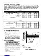
Fig. 9-2-21
*
The above remote control is one for cooling
only model.
9-3. Outdoor Unit
9-3-1. Accessory and Installation Parts
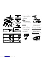
Hr.ON OFF TIMER
C
B
MODE
FAN
TEMP.
TEMP.
START/STOP
TIMER
WC-E1BE
ECONO.
ON
OFF
RSV
CNL
ACL CHK
FAN
SET
MODE
AUTO
AUTO
COOL
DRY
FAN ONLY
AUTO
LOW
MED.
HIGH
C
B
MODE button
CHK button
Required tools for installation work
1) Philips screw driver
2) Hole core drill (65 mm)
3) Spanner
4) Pipe cutter
5) Knife
6) Reamer
7) Gas leak detector
8) Tape measure
9) Thermometer
10) Mega-tester
11) Electro circuit tester
12) Hexagonal wrench (5 mm)
13) Flare tool
14) Pipe bender
15) Level vial
16) Metal saw
R410A (Special requirement)
17) Gauge manifold
(Charge hose : R410A special requirement)
18) Vacuum pump
(Charge hose : R410A special requirement)
19) Torque wrench
1/4 (17 mm) 16N•m (1,6 kgf•m)
3/8 (22 mm) 42N•m (4,2 kgf•m)
1/2 (26 mm) 55N•m (5,5 kgf•m)
20) Copper pipe gauge adjusting projection
margin
21) Vacuum pump adapter
TEMPORARY
TEMPORARY
button
Outdoor unit
installation manual x 3
Specifications x 3
Owner's manual x 1
1
2
3
4
Drain nipple x 1
(Heat pump model only)
SPECIFICATIONS
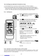
2. Setting of remote control selector at the
remote control side
[B] of the remote control is displayed with
liquid crystal only when it is set to [B].
There is no display of [A].
• Enter the battery.
• Push the [CHK] button by something with thin
edge. ([
] is displayed.)
• If [MODE] button is pushed while pushing
[CHK] button, the small [B] is displayed at the
right of the setting temperature indication
section.
*
To reset to [A] setting, push the [MODE]
button again while pushing the [CHK]
button.
3. Confirm the indoor unit can operate with
the changed setting of the remote control.
9-2-9. Check and Test Operation
¨
1. Check the unit is firmly hooked up on the
installation plate.
¨
2. Check the connecting pipes tightened
securely.
Confirm that there is no gas leakage.
¨
3. Confirm that all connecting cables are
secured and correct.
¨
4. Check the pipes insulation.
¨
5. Check the drainage.
¨
6. Connection of the grounding wire.
¨
7. To switch the TEST RUN (COOL) mode,
turn the switch on.
To switch the TEST RUN (COOL) mode,
press TEMPORARY button for 10 sec.
(The beeper will make a short beep.)
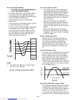
Fig. 9-2-22
¨
8. Operate the unit at cooling operation mode
for 15 minutes or more.
Measure the temperature of the intake and
discharge air. Ensure the difference
between the intake temperature and the
discharge one is more than 8°C.
NOTE:
Three-minutes protection feature
A protection feature prevents the air
conditioner from being activated for about
3 minutes when it is restarted immediately
after operation or when the power switch is
turned on.
¨
9. Check the remote control operation.
When finished the check and test operation,
make sure to return to REMOTE CONTROL.
(Push the TEMPORARY button with once
again.)
¨
10. Explain to the customer on the correct
usage of air conditioner with simple
layman’s terms.
9-3-2. Refrigerant Piping
• Piping kit used for the conventional refrigerant
cannot be used.
• Use copper pipe with 0,8 mm or more
thickness.
• Flare nut and flare works
• Flare nut and flare works are also different
from those of the conventional refrigerant.
Take out the flare nut attached to the main unit
of the air conditioner, and use it.
9-3-3. Installation Place
• A place which provides the spaces around the
outdoor unit.
• A place where the operation noise and
discharged air do not disturb your neighbors.
• A place which is not exposed to a strong wind.
• A place which does not block a passage.
• When the outdoor unit is to be installed in an
elevated position, be sure to secure its feet.
• There must be sufficient spaces for carrying
the unit into and out of the site.
• A place where the drain water does not raise
any problem.
CAUTION
1. Install the outdoor unit without anything
blocking the air discharging.
2. When the outdoor unit is installed in a
place exposed always to a strong wind like
a coast or on a high story of a building,
secure the normal fan operation using a
duct or a wind shield.
3. Specially in windy area, install the unit to
prevent the admission of wind.
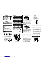
Strong
wind
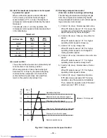
Fig. 9-3-1
4. Installation in the following places may
result in trouble. Do not install the unit in
such places.
• A place full of machine oil.
• A place full of sulfide gas.
• A place where high-frequency waves are
likely to be generated as from audio
equipment, welders, and medical
equipment.

