background image

– 11 –

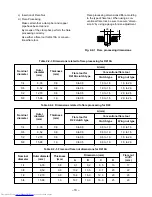
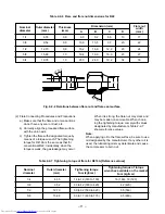
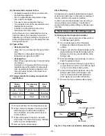
(2) Flare Connecting Procedures and Precautions

a) Make sure that the flare and union portions

do not have any scar or dust, etc.

b) Correctly align the processed flare surface

with the union axis.

c) Tighten the flare with designated torque by

means of a torque wrench. The tightening
torque for R410A is the same as that for
conventional R22. Incidentally, when the
torque is weak, the gas leakage may occur.

When it is strong, the flare nut may crack and
may be made non-removable. When choos-
ing the tightening torque, comply with values
designated by manufacturers. Table 2-2-7
shows reference values.

Note:

When applying oil to the flare surface, be sure to use
oil designated by the manufacturer. If any other oil is
used, the lubricating oils may deteriorate and cause
the compressor to burn out.

Table 2-2-7  Tightening torque of flare for R410A [Reference values]

Nominal

Outer diameter

Tightening torque

Tightening torque of torque

wrenches available on the market

diameter

(mm)

N•m (kgf•cm)

N•m (kgf•cm)

1/4

  6,35

14 to 18 (140 to 180)

16 (160), 18 (180)

3/8

  9,52

33 to 42 (330 to 420)

42 (420)

1/2

12,70

50 to 62 (500 to 620)

55 (550)

5/8

15,88

63 to 77 (630 to 770)

65 (650)

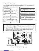
Fig. 2-2-2  Relations between flare nut and flare seal surface

Table 2-2-6  Flare and flare nut dimensions for R22

Nominal

Outer diameter

Thickness

diameter

(mm)

(mm)

1/4

  6,35

0,8

3/8

  9,52

0,8

1/2

12,70

0,8

5/8

15,88

1,0

3/4

19,05

1,0

Dimension (mm)

A

B

C

D

  9,0

  9,2

  6,5

13

17

13,0

13,5

  9,7

20

22

16,2

16,0

12,9

20

24

19,4

19,0

16,0

23

27

23,3

24,0

19,2

34

36

43˚

~

45˚

45˚

~

46˚

B

A

C

D

Flare nut

width

(mm)

Summary of Contents for RAS-M10YKCV-E

Page 1: ...SERVICE MANUAL FILE NO A00 9906 AIR CONDITIONER SUPPLEMENT SPLIT TYPE PRINTED IN JAPAN Nov 1999 ToMo RAS M10YKV E RAS M13YKV E RAS M18YAV E RAS M10YKCV E RAS M13YKCV E RAS M18YACV E R410A ...

Page 2: ...4 WIRING DIAGRAM 18 5 SPECIFICATIONS OF ELECTRICAL PARTS 21 6 REFRIGERANT CYCLE DIAGRAM 22 7 CONTROL BLOCK DIAGRAM 25 8 OPERATION DESCRIPTION 28 9 INSTALLATION PROCEDURE 41 10 HOW TO DIAGNOSE THE TROUBLE 49 11 HOW TO REPLACE THE MAIN PARTS 69 12 EXPLODED VIEWS AND PARTS LIST 80 ...

Page 3: ...l A unit liquid side gas side B unit liquid side gas side Maximum length per unit m Maximum length total m Maximum chargeless length m Maximum height difference m Refrigerant Name of refrigerant Weight kg Wiring connection Power supply Interconnection Usable temperature range Indoor Cooling Heating C Outdoor Cooling Heating C Accessory Indoor unit Installation plate Wireless remote control Label R...

Page 4: ...it Unit model A unit liquid side gas side B unit liquid side gas side Maximum length per unit m Maximum length total m Maximum chargeless length m Maximum height difference m Refrigerant Name of refrigerant Weight kg Wiring connection Power supply Interconnection Usable temperature range Indoor C Outdoor C Accessory Indoor unit Installation plate Wireless remote control Label Remote control holder...

Page 5: ... 1 unit 220 2 units 1 unit 230 2 units 1 unit 240 2 units Heating The above specification values are those under the conditions Cooling indoor DB WB 27 19 C Cooling outdoor DB 35 C Heating indoor DB 20 C Heating outdoor DB WB 7 6 C Operating Unit capacity Heating Running Power Outdoor indoor unit kW capacity current consumption operating noise A B A B kW A W dB 10 4 0 4 0 6 94 1450 45 0 7 to 5 2 1...

Page 6: ...DB27 C Outdoor DB35 C Indoor air flow High Pipe length 5m 2 2 units operating Conditions Indoor DB27 C WB19 C Indoor air flow High Pipe length 5m 2 2 units operating Current Limited Start 10 9 8 7 6 5 4 3 2 1 0 Current A 12 10 8 6 4 2 0 Current A 10 Compressor speed rps Compressor speed rps 0 20 30 40 50 60 70 80 90 100 0 20 40 60 80 100 120 140 Conditions Indoor DB 27 C WB 19 C Outdoor DB 35 C Ai...

Page 7: ...MCA ICF MOCP Ph Amps 9 56 9 56 15 50 230 1 198 264 14 31 14 31 15 13 47 13 47 15 13 81 13 81 15 Compressor Fan motor FLA MSC RLA Indoor Outdoor 7 13 7 13 0 15 x 1 0 15 0 50 10 93 10 93 0 15 x 1 0 15 0 50 10 14 10 14 0 15 x 2 0 30 0 50 10 41 10 41 0 15 x 2 0 30 0 50 NOTE Model of Indoor unit 10 RAS M10YKV E RAS M10YKCV E 13 RAS M13YKV E RAS M13YKCV E MCA Minimum Circuit Amps ICF Maximum Instantaneo...

Page 8: ...re as shown in Table 2 2 1 Never use copper pipes thinner than 0 8 mm even when it is available on the market This air conditioner adopts the new refrigerant HFC R410A which does not damage the ozone layer The working pressure of the new refrigerant R410A is 1 6 times higher than conventional refrigerant R22 The refrigerating oil is also changed in accordance with change of refrigerant so be caref...

Page 9: ...et joints are such that they are brazed for connections and used mainly for thick pipings whose diameter is larger than 20 mm Thicknesses of socket joints are as shown in Table 2 2 2 2 2 2 Processing of Piping Materials When performing the refrigerant piping installation care should be taken to ensure that water or dust does not enter the pipe interior that no other oil other than lubricating oils...

Page 10: ...e 2 2 4 Dimensions related to flare processing for R22 Nominal Outer Thickness diameter diameter mm mm 1 4 6 35 0 8 3 8 9 52 0 8 1 2 12 70 0 8 5 8 15 88 1 0 A mm Flare tool for Conventional flare tool R22 clutch type Clutch type Wing nut type 0 to 0 5 0 5 to 1 0 1 0 to 1 5 0 to 0 5 0 5 to 1 0 1 0 to 1 5 0 to 0 5 0 5 to 1 0 1 5 to 2 0 0 to 0 5 0 5 to 1 0 1 5 to 2 0 A ØD c Insertion of Flare Nut d F...

Page 11: ...ed by the manufacturer If any other oil is used the lubricating oils may deteriorate and cause the compressor to burn out Table 2 2 7 Tightening torque of flare for R410A Reference values Nominal Outer diameter Tightening torque Tightening torque of torque wrenches available on the market diameter mm N m kgf cm N m kgf cm 1 4 6 35 14 to 18 140 to 180 16 160 18 180 3 8 9 52 33 to 42 330 to 420 42 4...

Page 12: ...ls Conventional tools can be used In addition to the above exclusive tools the following equipments which serve also for R22 are necessary as the general tools 1 Vacuum pump Use vacuum pump by attaching vacuum pump adapter 2 Torque wrench For Ø6 35 3 Pipe cutter Tools exclusive for R410A The following tools for R410A are required Tools whose specifications are changed for R410A and their interchan...

Page 13: ... gas side Recover the refrigerant and check no refrigerant remains in the equipment For refrigerant charging see the figure below Connect the charge hose of the vacuum pump adapter Open fully both packed valves at liquid and gas sides Place the handle of the gauge manifold Low in the fully opened position and turn on the vacuum pump s power switch Then evacuating the refrigerant in the cycle When ...

Page 14: ... use the same type of brazing filler Fig 2 4 2 R410A refrigerant is HFC mixed refrigerant Therefore if it is charged with gas the compo sition of the charged refrigerant changes and the characteristics of the equipment varies 2 5 Brazing of Pipes 2 5 1 Materials for Brazing 1 Silver brazing filler Silver brazing filler is an alloy mainly composed of silver and copper It is used to join iron copper...

Page 15: ...g it is effective to proceed with brazing while letting dry Nitrogen gas N2 flow Never use gas other than Nitrogen gas 1 Brazing method to prevent oxidation Attach a reducing valve and a flow meter to the Nitrogen gas cylinder Use a copper pipe to direct the piping material and attach a flow meter to the cylinder Apply a seal onto the clearance between the piping material and inserted copper pipe ...

Page 16: ... 47 10 50 790 Knock out system Front panel Back body 232 326 232 Hanger 321 Drain hose 0 54m Connecting pipe 0 39m External length reference Flare ø6 35 Flare ø9 52 Hanger Connecting pipe 0 49m 659 65 5 344 326 450 65 5 For stud bolt ø8 ø10 For stud bolt ø6 Hanger Minimum distance to wall Minimum distance to ceiling 265 178 5 20 20 37 40 5 60 5 790 126 269 319 10 5 76 Center line Hanger Hanger 3 5...

Page 17: ...For sunshade roof attaching Fan guard Valve cover Earth terminal B leg part Hanger ø6 hole pitch Anchor bolt long hole pitch A leg part view Z Charging port 2 ø6 hole 2 ø6 hole 600 50 11 R15 36 310 296 600 50 11 R15 36 310 296 R 5 5 R 5 5 Detailed A leg part Detailed B leg part Outside line of product Outside line of product 600 310 B C A D 4 ø11 17U shape hole For ø8 ø10 anchor bolt Mounting dime...

Page 18: ...r voltage at the lead of louver motor Check the transformer and the rated voltage power supply circuit Check for voltage at the CN10 connector side point Check the transformer and the rated voltage power supply circuit MAIN P C BOARD MCC 772 BLK P04 CN30 CN23 INDOOR TERMINAL BLOCK INDOOR UNIT OUTDOOR UNIT CN07 CN10 TO1 DC35V DC12V DC7V DC0V C06 C02 IC04 R116 C15 R21 J04 F01 FUSE T6 3A 250V R109 VA...

Page 19: ...OR L03 To INDOOR UNIT A To INDOOR UNIT B TD WHI YEL ORN BLU RED GRY P M V B UNIT WHI YEL ORN BLU RED GRY ORN REACTOR WHI CN501 P12 P13 P11 P14 YEL YEL PUR CN704 BLK BLK PNK YEL RED WHI BLK GRY P04 RED P05 WHI BRW RED ORN YEL BLK BRW RED ORN YEL P06 CN15 P02 GRY P01 L 3 2 1 3 2 1 1 2 3 1 2 3 4 4 5 5 1 1 2 2 3 3 2 2 1 1 N 1 2 3 1 2 3 1 1 2 2 CN02 WHI CN03 WHI CN04 BLK CN05 YEL CN14 CN13 1 1 2 2 3 3 ...

Page 20: ...DOOR UNIT A To INDOOR UNIT B TD WHI YEL ORN BLU RED GRY P M V B UNIT WHI YEL ORN BLU RED GRY ORN REACTOR WHI CN501 P12 P13 P11 P14 YEL YEL PUR CN704 BLK BLK PNK YEL RED WHI BLK GRY P04 RED P05 WHI BRW RED ORN YEL BLK BRW RED ORN YEL P06 CN15 P02 GRY P01 L 3 2 1 3 2 1 1 2 3 1 2 3 4 4 5 5 2 2 1 1 N 1 2 3 1 2 3 1 1 2 2 CN02 WHI CN03 WHI CN04 BLK CN05 YEL CN14 CN13 1 1 2 2 3 3 1 1 2 2 1 1 2 2 1 1 2 2 ...

Page 21: ...0 7 DC140V 40W 6 Fan control relay AJQ1341 Coil DC12V Contact AC125V 3A 7 Suction temp sensor Inverter attached 10kΩ 25 C TS sensor 8 Discharge temp sensor Inverter attached 62kΩ 20 C TD sensor 9 Outside air temp sensor Inverter attached 10kΩ 25 C TO sensor 10 Temp sensor at A room Inverter attached RAS M18YACV E 10kΩ 25 C gas side TGa sensor RAS M18YAV E 62kΩ 20 C 11 Terminal block 9P 20A AC250V ...

Page 22: ... Refrigerant flow Heating INDOOR UNIT T1 Temp measurement To B room Indoor heat exchanger Cross flow fan Deoxidized copper pipe Both A and B rooms Outer dia 6 35mm Thickness 0 8mm Sectional shape of heat insulator To B room Allowable height difference 10m Allowable pipe length Per 1 unit Max 20m Total 30m P Pressure measurement Gauge attaching port Vacuum pump connecting port Deoxidized copper pip...

Page 23: ...y Ø2 2 x 200 Pulse modulating valve at liquid side SEV15RC2 Muffler Ø25 x 80 Ø1 5 x 200 Ø1 5 x 200 TGa TD Accumulating tank Ø51 x 200 290cc Compressor DA130A1F 21F TS Outdoor heat exchanger Split capillary Propeller fan Refrigerant amount 1 15kg OUTDOOR UNIT Muffler Ø25 x 80 T1 Temp measurement T2 Temp measurement TE Table 6 1 2 Total length in two rooms Each length in one room Unnecessary to add ...

Page 24: ...ature No of condition C operating Indoor Outdoor units 1 unit 27 19 35 2 units Operating combination Standard Unit pressure A B P MPa M13YKCV E 0 7 to 0 9 M13YKV E M10YKCV E 0 9 to 1 1 M10YKV E M13YKCV E M10YKCV E 0 8 to 1 0 M13YKV E M10YKV E M10YKCV E M10YKCV E 0 8 to 1 0 M10YKV E M10YKV E Heat exchanger Indoor Outdoor Compressor pipe temp fan fan revolution T1 C T2 C mode mode rps 9 to 11 46 to ...

Page 25: ...xchanger Sensor Temperature Sensor Infrared Rays Signal Receiver Initializing Circuit Clock Frequency Oscillator Circuit Power Supply Circuit Infrared Rays Remote Control Operation START STOP Thermo Setting Fan Speed Selection ON TIMER Setting OFF TIMER Setting Louver AUTO Swing Louver Direction Setting ECONO Operation Mode Selection AUTO COOL DRY HEAT Infrared Rays Remote Control Operation START ...

Page 26: ...tor correction control Signal communication to MCU M C U Input current Sensor Over current sensor Over current sensor Converter AC DC Noise filter High power factor correction circuit Over current detect circuit Over current detect circuit Rotor position detect circuit Rotor position detect circuit Gate drive circuit Gate drive circuit Inverter output frequency control A D converter function P M V...

Page 27: ...Signal communication to MCU M C U Input current Sensor Over current sensor Over current sensor Converter AC DC Inverter DC AC Inverter DC AC Noise filter High power factor correction circuit Over current detect circuit Over current detect circuit Rotor position detect circuit Rotor position detect circuit Gate drive circuit Gate drive circuit Inverter output frequency control A D converter functio...

Page 28: ...ressor is two times cycles of the actual number of revolution 1 Role of indoor unit controller The indoor unit controller judges the operation commands from the remote control and as sumes the following functions Judgment of suction air temperature of the indoor heat exchanger by using the indoor temp sensor Temperature setting of the indoor heat ex changer by using heat exchanger sensor Prevent f...

Page 29: ...changing supply power status to the compressor with transis tor module includes 6 transistors The outline of the control is as follows The revolution position and revolution speed of the motor are detected by detecting winding electromotive force of the com pressor motor under operation and the revolution speed is changed so that the motor drives based upon revolution speed of the operation comman...

Page 30: ...louvers are auto matically controlled according to the operation status AUTO COOL DRY HEAT Besides positions of vertical air flow louvers can be arbitrarily set by pressing the SET button The louver position which has been set by the SET button is stored in microcomputer and the louver is automatically set at the stored position in the next operation 2 Swing If the AUTO button is pressed during ru...

Page 31: ...When pushing START STOP button of the remote control receive sound is issued from the main unit and the next operations are performed together with opening the vertical air flow louvers 8 2 1 Fan Only Operation The Remote Control MODE Button is Set to the FAN ONLY Operation Once the setting is made the operation mode is memorized in the microcomputer so that the same operation can be effected ther...

Page 32: ... operated at fan speed L as shown in Fig 8 2 2 while the outdoor unit stops 2 Prevent freezing control If temperature of indoor heat exchanger de tected by the indoor heat exchanger sensor is 5 C or lower compressor motor speed is gradually lowered to prevent freezing of the indoor heat exchanger If temperature is 7 C or higher return the operation to the above item 1 3 Current release control The...

Page 33: ...y up 3 Control 3 C zone Keep zone When TD detect value is 108 C or higher operating motor speed is not changed if raising operation speed 4 Control 4 D zone Slow down zone of motor speed When TD detect value is 111 C or higher operating motor speed is slowly down 5 Control 5 E zone Normal down of motor speed When TD detect value is 115 C or higher operating motor speed is down 6 Control 6 F zone O...

Page 34: ... 3 5 Room temp Set temp Air volume Compressor motor speed 13 rps 13 rps SUL 20 rps 16 rps L 13 to 20 rps 13 to 16 rps UL M13 M10 Time 2H 1H 8 2 3 DRY Operation The Remote Control MODE Button is Set to the DRY Position Once the setting is made the operation mode is memorized in the microcomputer so that the same operation can be effected thereafter simply by pushing START STOP button Dry operation ...

Page 35: ...door unit and also controls revolution speed of the compres sor motor The power coupler IC20 for four way valve is turned on and turned off in defrost operation 1 Heating capacity control Calculate the difference between temperature detected by room temp sensor every minute and the set temp set on Temp indicator and variation amount of room temp Then obtain the correction amount of the command sig...

Page 36: ... minutes Setting on remote control HEAT mode HIGH Fan 30 C temp Room temp is 19 C to 24 C and outside air temp is 5 C or lower Defrost operation has been already performed once 2 Defrost operation Operation of the compressor is stopped once turn off power coupler for four way valve after 10 seconds and then exchange the four way valve After 10 seconds restart operation of the compressor Turn off t...

Page 37: ...ic Operation 1 As shown in Fig 8 2 10 the operation mode COOL DRY HEAT is selected according to the outside temperature when the operation has started The operation in Fan mode continues until an operation mode is selected If the room temperature is 20 C or higher when AUTO operation started within 2 hours after HEAT operation had stopped select an opera tion mode after Fan operation of ultra low ...

Page 38: ... restart automatically The above Auto Restart settings can be carried out When the system is stand by not operating When the system is operating Operation Push the TEMPORARY button continuously more than three seconds Motion Stand by The system starts to operate The green light goes on about three seconds after The unit beeps three times The orange light goes on The system is operating If the syst...

Page 39: ...nuously more than three seconds Motion Operating The orange light goes on The system stops to operate The orange light goes off about three seconds after The unit beeps three times The system stops If the system is not required to stop at this time use the remote control and to restart During subsequent operation the green light goes on TEMPORARY 0 3S TEMPORARY 0 3S 2 If OFF TIMER operation is res...

Page 40: ...icated when the ECONO button is pushed Set time for timer operation is indicated Set temperature is indicated 17 C to 30 C Selected degree of air flow HIGH MED LOW or AUTO is indicated MODE FAN FANONLY AUTO COOL DRY AUTO LOW MED HIGH Hr ONOFFTIMER C B Transmitter MODE TEMP FAN START STOP ON OFF RSV CNL FANONLY AUTO COOL DRY AUTO LOW MED HIGH TIMER ACL CHK MODE ECONO Hr ONOFFTIMER C B TEMP AUTO SET...

Page 41: ...npacking the unit examine it carefully for possible damage Do not install in a place that can increase the vibration of the unit Do not install in a place that can amplify the noise level of the unit or where noise and discharged air might disturb user s neighbors To avoid personal injury be careful when handling parts with sharp edges Please read the installation manual carefully before installin...

Page 42: ...iagram A place where there is no obstacle near the air inlet and outlet A place which allows an easy installation of the piping to the outdoor unit A place which allows the front panel to be opened CAUTION Direct sunlight to wireless receiver of the indoor unit should be avoided The microprocessor in the indoor unit should not be too close to r f noise sources Remote Control A place where there ar...

Page 43: ...th line to the metallic part mark located at the side of 3P terminal Fig 9 2 9 9 2 5 Piping and Drain Hose Installation In case of rightward piping After scribing slits of the front cabinet and the rear panel by a knife or a marking off pin cut them by a pair of nippers or the like Slit rear panel Slit front cabinet Slit rear panel Slit front cabinet 196mm 96mm Liquid side Gas side Outward form of...

Page 44: ...of the front cabinet toward you to remove it from the rear panel How to remove the front cabinet 5 5 2 3 Vertical air flow louver 4 2 3 How to open the screw cap Fig 9 2 18 Place your finger on the lower part and push to open the screw cap Remove the connector cover 1 Remove the screws securing the connector cover Remove the electrical parts cover 1 Remove the screws securing the electrical parts ...

Page 45: ...mode press TEMPORARY button for 10 sec The beeper will make a short beep Fig 9 2 22 8 Operate the unit at cooling operation mode for 15 minutes or more Measure the temperature of the intake and discharge air Ensure the difference between the intake temperature and the discharge one is more than 8 C NOTE Three minutes protection feature A protection feature prevents the air conditioner from being a...

Page 46: ... Outdoor unit 10 m or less A B Valve cover Fixing bolt arrangement of outdoor unit Fig 9 3 6 Secure the outdoor unit with the fixing bolts and nuts if the unit is likely to be exposed to a strong wind Use ø8 mm or ø10 mm anchor bolts and nuts Drainage Fig 9 3 7 Install the provided drain nipple in the hole of the bottom plate Perform proper drainage processing using a drain hose sold separately or...

Page 47: ...n the valve stem all the way out so not try to open it beyond the stopper Securely tighten the valve stem cap torque is as follows Compound pressure gauge Pressure gauge Manifold valve Handle Hi Keep full closed Charge hose For R410A only Vacuum pump adapter for counter flow prevention For R410A only Packed valve at liquid side Packed valve at gas side Service port Valve core Setting pin Connectin...

Page 48: ...r more troubles occur LEDs go on cyclically alternately 3 Usually LEDs Red go off Flare nut connections Outdoor unit Valve stem cap connection Service port cap connection Flare nut connections Indoor unit Wiring port D11 D12 D13 D14 D15 LED Red 9 3 13 Installation Servicing Tools Changes in the product and components In the case of an air conditioner using R410A in order to prevent any other refri...

Page 49: ...outdoor unit controller inverter Therefore if the power supply is turned off charge charging voltage DC280V remains and discharging takes a lot of time After turning off the power source if touching the charging section before discharging an electri cal shock may be caused Discharge the electrolytic capacitor completely by using soldering iron etc Discharging method 1 Remove the inverter cover pla...

Page 50: ...nutes respectively after the operation has started If the set value is above the room temperature Cooling operation is not performed And check whether battery of the remote control is consumed or not After selecting Cool or Heat mode select an operation mode again if the compressor keeps stop status for 15 minutes The compressor motor speed may decrease by high temp release control Release protect...

Page 51: ...ER FAN ONLY Item A B C D E Check code Block display Description for self diagnosis 10 3 Judgment by Flashing LED of Indoor Unit While the indoor unit monitors the operation status of the air conditioner if the protective circuit operates the contents of self diagnosis are displayed with block on the indoor unit indication section Table 10 3 1 If there is any trouble on the outdoor unit side the de...

Page 52: ...O COOL DRY AUTO LOW MED HIGH TIMER ACL CHK MODE ECONO Hr ONOFFTIMER C B TEMP AUTO SET FAN Alphanumeric characters are used for the check codes is 5 is 6 is A is B is C is D 1 2 3 TIMER ACL CHK E START STOP 10 4 Self Diagnosis by Remote Control Check Code 1 The self diagnosis by the check code is performed while items B to E blocks are displayed 2 When turning the operation mode on the remote contr...

Page 53: ... supply gas check gas leak also 3 Unit operates normally during check If Return serial signal does not stop between indoor terminal board 2 and 3 replace inverter P C board If signal stops between indoor terminal board 2 and 3 replace indoor P C board If Operation command signal does not stop between indoor terminal board 2 and 3 replace inverter P C Air conditioner status Operation continues Oper...

Page 54: ...gnal is reset Displayed when error is detected Displayed when error is detected Displayed when error is detected Judgment and action Even if trying operation again all operations stop immediately Replace P C board 1 Even if connecting lead wire of compressor is removed position detect circuit error occurred Replace P C board 2 Measure resistance between wires of compressor and perform short circui...

Page 55: ...SW trans T01 applied YES Is DC35V DC12V DC7V applied to secondary side of SW trans T01 applied To item of Pre check or trouble before power board Remote control error Replace main board Replace temp fuse set Check connecting wire Microcomputer is defective Turn OFF breaker once and ON again after removing motor SW trans IC IC01 for power supply or fan motor Motor is defective Refer to the item of ...

Page 56: ...n rotate normally Repair the bearing of the cross flow fan Turn on the power supply Is the rotation signal DC 5V 0V output between 4 blue lead wire and 2 black lead wire of the motor connector CN10 when rotating the cross flow fan by hand in no operating status 2 pulses one turn Replace the control board Turn off the power supply and turn it on after removing the motor from the board Is the voltag...

Page 57: ...urning on power supply alone Operation may be normally performed selected by operation on the remote control Cause IC is built in the indoor fan motor therefore P C board is also mounted to inside of the motor If soldering of P C board in the motor is defective or IC is defective the fan motor may rotate by only inputting the power turning on power supply Confirmation procedure 1 Remove the front ...

Page 58: ...ng within 5cm distance from the radio Does the transmission indicator light Short circuit ACL switch with a coin or others at rear side of remote control Cooling only model Heat pump model Replace P C board Replace the battery Normal Remote control is failure NO YES NO YES NO YES NO YES NO YES NO YES NO YES Is Temporary Cool operation possible when keeping the temporary switch of the air condition...

Page 59: ...ck varied Confirm that transmission from indoor to outdoor is correctly performed based upon the following dia gram NOTE Measurement should be performed 2 minutes and 30 seconds after starting of the operation Be sure to prepare a diode for judgment Fig 10 5 1 Normal time Voltage swings between DC15 and 60V Abnormal time Voltage does not vary 2 Outdoor unit stops in a little while after operation ...

Page 60: ...at outlet 1 4 inch Ø6 35mm valve side the valve is clogged Is positioning sound of valve sound hitting to stopper heard from valve when the air conditioner starts the operation after turning off power of the air conditioner once NOTE After all the operations stopped by the remote control the power keeps being supplied to outdoor unit for approx 3 minutes If operating the air conditioner by remote ...

Page 61: ...essor thermo operation instantaneous power failure gas leak IGBT short circuit compressor motor rear short Position detect circuit error Current detect circuit error Outdoor heat exchanger temp sensor TE error Suction temp sensor TS error Discharge temp sensor TD error Outdoor fan error Outside temp sensor TO error Compressor system error A room gas side temp sensor TGa error Gas leakage TS sensor...

Page 62: ...nd diode block DB01 Connect discharge resistance approx 100Ω40W or soldering iron plug between terminals of the electro lytic capacitor 500µF of C15 with printed CAU TION HIGH VOLTAGE on P C board If 15A fuse is blown discharge both edges of the electrolytic capacitor with soldering iron OK if 500µF DC140V Remove CN300 while pushing the part indicated by an arrow because CN01 is a connector with l...

Page 63: ... compressor Check fan motor position detect signal Replace com pressor C B A Replace outdoor fan motor Replace control board assembly Replace control board Replace compressor Check compressor winding resistance 10 9 How to Check Simply the Main Parts 10 9 1 How to Check the P C Board Indoor Unit 1 Operating precautions 1 When removing the front panel or the P C board be sure to shut off the power ...

Page 64: ...age check 1 Voltage of relay coil DC 12V Between pin 10 of IC31 and GND Between pin 11 of IC31 and GND 2 Between No 1 and 2 of connecting cable terminal block 220 230 240V AC 1 All indicators light for 3 sec 2 Indicators do not indicate normally after approximate 3 sec 1 Compressor does not operate 2 OPERATION lamp flashes 1 The voltage of DC 35V is not measured between the red and black of the mo...

Page 65: ...a Gas side temp sensor TA Room temp sensor TC Heat exchanger temp sensor TO Outdoor temp sensor TE Outdoor heat exchanger temp sensor TS Suction temp sensor TA TC TO TE TS TD TGa Heat pump model Cooling only model TGa 10 9 2 P C Board Layout Bottom View For the Top View refer to page 71 1 Sensor characteristic table ...

Page 66: ...erature sensor TO pipe temperature sensor TGa discharge temperature sensor TD suction tempera ture sensor TS outdoor heat exchanger temperature sensor TE Checking procedure Measure the resistance value of each winding by using the tester Measure the resistance value of winding by using the tester For details refer to Section 10 10 Check conduction by using the tester Disconnect the connector and m...

Page 67: ...C13 C14 C15 500µF 400V 1 Turn OFF the power supply breaker 2 Discharge all four capacitors completely 3 Check that the normal rectification characteristics are shown in continuity test by the tester MCC 758 Soldered surface Heat sink IGBT side C12 C13 C14 C15 Case that product is good Pointer swings once and returns slowly When performing test once again under another polarity the pointer should r...

Page 68: ...otor does not rotate Outdoor fan motor stops within several tens seconds though it started rotating Outdoor fan motor rotates or does not rotate according to the position where the fan stopped etc Remote control check code 02 Outdoor block 1A Outdoor fan drive system error 2 Cause The following causes are considered when the outdoor fan motor does not normally rotate 1 Mechanical lock of the outdo...

Page 69: ...ing operation is performed without pressing the center of the air outlet the surface of the front panel may be covered with frost and have a waterdrop 1 Perform the process above 2 Remove the screw securing the shield metal plate 3 Remove the electrical part cover by pressing the nail located on upper portion of the electrical part cover 4 Remove the drain guide 5 Remove the screw securing to the ...

Page 70: ...ng the heat exchanger slightly to the right side 1 Perform the process 2 Loosen the set screw of the cross flow fan 3 Remove the screw fixing the shaft bearing base 4 Lift slightly up the left side of the heat exchanger and pull the shaft bearing base out left downwards When assembling it fix it with the set screw on the position where the gap between the rear plate surface and the left end surfac...

Page 71: ...onditioner 2 Remove the front panel Remove the two fixing screws φ4 x 14l l l l l 3 Remove the electrical part base No Remarks Replace the thermal fuse terminal block microcomputer ass y and the P C board ass y Part name Common procedure 11 2 Microcomputer P C board layout ...

Page 72: ...ole and then fix it with screw ST1TØ4 x 10l l l l l 1 pc 3 Attach the valve cover ST1TØ4 x 10l l l l l 1 pc Insert the upper part to the upper cabinet set hook claw of the valve cover to square holes at three positions of the main unit and attach it pushing upward 1 Detachment 1 Perform work of item 1 of 2 Remove screws ST1TØ4 x 10l l l l l 1 pc of the front cabinet and inverter cover and screws S...

Page 73: ...olytic capacitor 500µF on P C board Be careful to discharge the capacitor because the electrolytic capacitor cannot naturally discharge and voltage remains according to trouble type in some cases NOTE This capacitor is one with mass capacity Therefore it is dangerous that a large spark generates if short circuiting be tween polarity with screwdriver etc for discharging 4 Remove screw ST1TØ4 x 10l ...

Page 74: ...01 TE sensor 2P White CN02 TD sensor 3P White CN04 TS sensor 3P Black CN05 TGa sensor 3P Yellow CN08 Case thermo 2P White CN13 B room pulse modulating valve 6P Red CN14 A room pulse modulating valve 6P Black 2 Disconnect cable connecting the main control board assembly side and sub control board assembly Main control board assembly side CN704 Connecting cable 4P White Sub control board assembly si...

Page 75: ...ve the sound insulation material 5 Remove terminal cover of the compressor and disconnect lead wire of the compressor thermo and the compressor from the terminal 6 Remove pipe connected to the compressor with a burner 7 Remove the fixing screw of the bottom plate and heat exchanger ST1TØ4 x 10l 1 pc 8 Remove the fixing screw of the bottom plate and valve clamping plate ST1TØ4 x 10l 2 pcs 9 Pull up...

Page 76: ...d marking is marked on the pulse modulat ing valve is connected to CN13 of the control board assembly 1 Detachment 1 Perform work of item 1 of and 2 Remove the front cabinet and put it down so that fan guard side directs downward Perform work on a corrugated cardboard cloth etc to prevent flaw to the product 3 Remove the hooking claws by pushing minus screwdriver according to the arrow mark in the...

Page 77: ...or and sensor sides and solder them 8 Move the thermal constringent tubes toward the soldered parts and heat them with the dryer and constring them 9 Wind the attached color tape round the both terminals of the protective tube when colored protective tube is used 10 Fix the sensor again NOTES 1 Store the joint part of the sensor and the connector in the electric parts box 2 Never joint them near t...

Page 78: ... 78 MCC 758 ...

Page 79: ... 79 MCC 775 ...

Page 80: ...tion No No 408 43T69047 P C Board Assembly MCC 772 M13YKCV E 409 43T69050 P C Board Assembly MCC 772 M13YKV E 410 43T69049 P C Board Assembly MCC 772 M10YKV E 412 43T61001 Base E Parts ABS Black UL94 5V 413 43T62006 Base Shield SGCC Z08 LUB Location Part Description No No 12 EXPLODED VIEWS AND PARTS LIST 12 1 Indoor Unit 1 RAS M10 M13YKV E RAS M10 M13YKCV E 402 403 407 RAS M10YKCV E 408 RAS M13YKC...

Page 81: ...er Sensor Location Part Description No No Location Part Description No No 220 43T49003 Spring 221 43T49028 Plate EVA SEAL 222 43T49023 Holder of Plate of EVA SEAL 224 43T79002 Drain Guide 225 43T39002 Motor Band Left 226 43T39001 Motor Band Right 227 43T21010 Fan Motor 228 43T20007 Fan Cross Flow 229 43T22002 Bearing 230 43T39003 Base Bearing 231 43T03001 Rear Plate 232 43T07002 Pipe Holder 233 43...

Page 82: ...2 13 43147196 Bonnet 1 4 IN 14 43047401 Bonnet 3 8 IN 15 43047491 Tube Capillary I D 1 5 16 43146448 Tube Capillary 17 43046351 Valve Pulse Modulating Location Part Description No No Location Part Description No No 18 43046347 Coil P M V 19 43058264 Reactor 20 43050298 Thermo Bimetal CS 7 21 4302C019 Motor Fan DC 22 43047549 Nut Flange 23 43020310 Fan Propeller 24 43097166 Nut 25 43049643 Cushion ...

Page 83: ...ption No No 710 4306S180 P C Board Assembly MCC 758 M18YACV E 710 4306S181 P C Board Assembly MCC 758 M18YAV E 711 4306S177 P C Board Assembly MCC 775 M18YACV E 711 4306S178 P C Board Assembly MCC 775 M18YAV E 712 43050398 Sensor TGa F4 M18YAV E 4 4 3 2 1 4 3 2 1 709 710 708 705 707 711 703 TO Sensor TE Sensor Ø6 TS Sensor TGa Sensor Ø4 TD Sensor Ø4 Heat pump model Cooling model 702 702 712 704 70...

Page 84: ......

Reviews: