


– 54 –
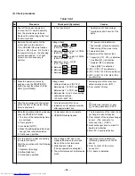
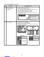
Check
Cause of operation
code
Inverter over-current
protective circuit operates.
(Short time)
Position-detect circuit
error or short-circuit
between windings of
compressor
Current-detect circuit
error
Being out of place,
disconnection or short-
circuit of outdoor temp.
sensor
Disconnection or short-
circuit of exhaust temp.
sensor
Outdoor fan drive system
error
Outdoor heat exchanger
temp. sensor error
Compressor drive output
error, Compressor error
(lock, missing, etc.),
Break down
Error exclusive for
multiple type
Return serial signal has
been sent when operation
started, but it is not sent
from halfway.
(1) Compressor thermo.
operation
Gas shortage
Gas leak
(2) Instantaneous power
failure
Compressor does not
rotate. (Current protective
circuit does not operate
when a specified time
passed after compressor
had been activated.)
Discharge temp.
exceeded 120°C.
Break down of
compressor
Four-way valve inverse
error (TC sensor value
lowered during heating
operation.)
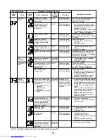
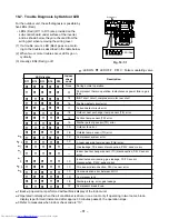
Operation of diagnosis function
Block distinction
Check
Block
code
Outdoor P.C.
board
Not
displayed
Outdoor P.C.
board
Others
(including
compressor)
Air
conditioner
status
All off
All off
All off
All off
All off
All off
Operation
continues.
All off
All off
Operation
continues.
All off
All off
All off
Operation
continues.
Remarkes
Displayed when
error is detected.
Displayed when
error is detected.
Displayed when
error is detected.
Displayed when
error is detected.
Displayed when
error is detected.
Displayed when
error is detected.
——
Displayed when
error is detected.
Displayed when
error is detected.
Flashes when
trouble is detected
on Return serial
signal, and normal
status when signal
is reset.
Displayed when
error is detected.
Displayed when
error is detected.
Displayed when
error is detected.
——
∗
Judgment and action
Even if trying operation again, all
operations stop immediately. :
Replace P.C. board.
1. Even if connecting lead wire of
compressor is removed, position-
detect circuit error occurred. :
Replace P.C. board.
2. Measure resistance between wires
of compressor, and perform short-
circuit. : Replace compressor.
Even if trying operation again, all
operations stop immediately. : Replace
P.C. board.
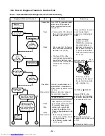
Check 5-serial LED.
1. Check outdoor temp. sensors
(TE, TS).
2. Check P.C. board.
1. Check discharge temp. sensor
(TD).
2. Check P.C. board.
Position-detect error, over-current
protective operation of outdoor fan
drive system, fan lock, etc. : Replace
P.C. board or fan motor.
1. Check outdoor heat exchanger
temp. sensor (TE).
2. Check P.C. board.
Check 5-serial LED.
When 20 seconds passed after start-
up, position-detect circuit error
occurred. : Replace compressor.
Check 5-serial LED.
1. Miswiring of connecting wire of A/
B rooms in indoor/outdoor units
2. Check gas leakage.
3. Check disconnection of sensor.
4. Electronic control valve error
1. Repeat Start and Stop with interval
of approx. 10 to 40 minutes. (Code
is not displayed during operation.)
Supply gas. (Check also gas leak).
2. Unit operates normally during
check.
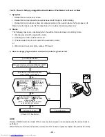
If Return serial signal does not
stop between indoor terminal block
2 and 3, replace inverter P.C.
board.
If signal stops between indoor
terminal block 2 and 3, replace
indoor P.C. board.
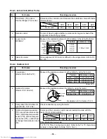
1. Trouble on compressor
2. Trouble on wiring of compressor
(Missed phase)
1. Check dischage temp. sensor (TD).
2. Degassing
3. Trouble on P.M.V.
1. Check power voltage.
(220–230–240 V ±10%)
2. Overload operation of refrigeration
cycle
Check installation condition
(Short-circuit of outdoor diffuser).
1. Check four-valve operation.
∗
For 1C and 1E marked with
∗
, refer to the column in page 60.