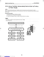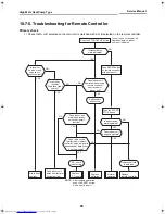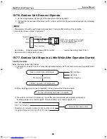
High Wall, Heat Pump Type
Service Manual
70
Toshiba
9-5-4. Select Switch on Remote
Controller
• If two indoor units are installed in the same room or
adjoining rooms, when the user tries to operate only
one unit, both units may receive the same remote
controller signal and operate. This can be prevented
by changing one of the indoor units and remote
controllers to setting “B” (the default setting for both
units is “A”).
• If the indoor unit and remote controller settings are
different, the remote controller signal is not
accepted.
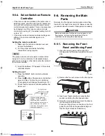
Setting the remote controller
1) Slide open the remote controller cover and
remove the batteries.
2) Cut the jumper wire inside the battery
compartment using nippers.
NOTE
The jumper wire should not remain in contact after
being cut. Also, be careful not to let plastic scraps,
jumper wire cuttings or other debris enter the inside of
the remote controller.
3) Insert the batteries. “B” appears in the remote
controller display.
Setting the unit
1) Press the RESET button to start automatic
operation.
2) Press the button of the remote controller that
was set in step 1 to stop the air conditioner.
(This operation will change the setting to “B”.)
3) Check that the remote controller operates the
indoor unit.
9-6. Removing the Main
Parts
Normally, the front panel, moving panel, and air flow
louvres do not need to be removed. However, use the
procedure below if removal of these parts is necessary.
CAUTION
Before removing the front panel, moving panel, or air
flow louvres, be sure to stop operation of the air
conditioner and unplug the power supply.
9-6-1. Removing the Front
Panel and Moving Panel
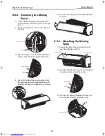
1) Open the moving panel, and support the
moving panel by the panel support on the right
side.
2) Remove the four set screws on the front panel.
3) Insert your thumb into the air outlet bottom
section, and lift up the front panel bottom.
4) Close the moving panel to remove the clips on
the top side as shown below.
Press your finger down on the clip on the front
panel top, and lift up the panel back edge so
that the clip is released (5 locations).
Jumper wire
Cutting direction
When switching between
settings “A” and “B”, always
switch the indoor unit board
and the remote controller as a
pair. (Otherwise, the indoor
unit will not accept the remote
controller’s signals.)
RESET button
Moving panel
Panel support
Front panel
Clip
Clip
Clip
Clip
Clip
+00A08-010_01EN_SVM_HighWallHeatPump.book Page 70 Wednesday, March 4, 2009 11:22 AM

