High Wall, Heat Pump Type
Service Manual
34
Toshiba
4) When AUTO operation has started within 2
hours after heating operation stopped and if the
room temperature is 20°C or more, the fan
operation is performed with ”Super Ultra LOW”
mode for 3 minutes.
Then, select an operation mode.
5) If the status of compressor-OFF continues for
15 minutes the room temperature after
selecting an operation mode (COOL/HEAT),
reselect an operation mode.
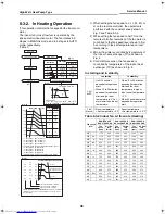
8-2-4. DRY Operation
DRY operation is performed according to the
difference between room temperature and the setup
temperature as shown below.
In DRY operation, fan speed is controlled in order to
prevent lowering of the room temperature.
1) Detects the room temperature (TA) when the
DRY operation started.
2) Starts operation under conditions in the above
figure according to the temperature difference
between the room temperature and the setup
temperature (Tsc).
Setup temperature (Tsc)
= Set temperature on remote controller (Ts)
+ (-1.5 to 2.0)
3) When the room temperature is lower 2°C or
less than the setup temperature, turn off the
compressor.
4) The time correction is performed every 8
minutes.
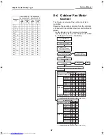
8-3. Indoor Fan Motor
Control
8-3-1. In Cooling Operation
(This operation controls the fan speed at indoor unit
side.)
The indoor fan (cross flow fan) is operated by the
phase control induction motor. The fan rotates in 5
stages in MANUAL mode, and in 5 stages in AUTO
mode, respectively.
(Table 1)
+2.5
TA-Tsc
[°C]
+2.0
+1.5
+1.0
+0.5
12
11
10
9
8
7
6
5
4
3
2
1
+4.5
+4.0
+3.5
+3.0
0.0
-0.5
-1.0
-1.5
-2.0
Zone Compressor speed (rps)
07
PKVP
10
PKVP
13
PKVP
16
PKVP
18
PKVP
0
Fan
Speed
Time
correction
35
30
25
15
10
10
20
35
30
25
15
10
10
20
41
35
29
17
10
11
23
45
38
32
18
10
12
25
50
42
35
20
10
12
27
OFF
OFF
OFF
OFF
OFF
W5
W4
W8
W6
+1 zone
±0
-1 zone
(min 1)
* Symbols
UH
: Ultra High
H
: High
M+
:
M
: Medium
L+
: Low+
L
: Low
L-
: Low–
UL
: Ultra Low
SUL
: Super Ultra Low
+2.5
TA-Tsc
[°C]
+2.0
+1.5
+1.0
+0.5
Tsc
a
b
c
d
e
M+(WC)
*3
*4
*5
L(W7)
L
L+
M
M+
H
W7
(L+M)/2
WA
(M+H)/2
WD
Indication Fan speed
Fan speed setup
COOL ON
AUTO
MANUAL
*3 : Fan speed = (M+–L)x3/4+L
*4 : Fan speed = (M+–L)x2/4+L
*5 : Fan speed = (M+–L)x1/4+L
*6 : Fan speed = (H–L+)x3/4+L+
*7 : Fan speed = (H–L+)x2/4+L+
*8 : Fan speed = (H–L+)x1/4+L+
(Linear approximation from M+ and L)
(Fig. 2)
(Fig. 1)
Hi Power
W8
(L+M)/2
(M+H)/2
WC
WE
H(WD)
Fan speed
Hi Power
*6
*7
*8
L+(W8)
+00A08-010_01EN_SVM_HighWallHeatPump.book Page 34 Wednesday, March 4, 2009 11:22 AM


