No.
Part name
P
rocedure
s
Remarks
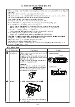
Drain pan
assembly
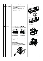
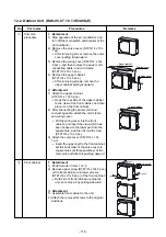
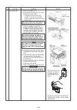
1) Follow the procedure item 3 .
2) Remove screw holding the electric part cover.
3)
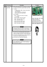
Disconnect the louver motor connector (5P)
from P.C. board assembly.
4)
Remove fixing screws of the unit display
and remove unit display.
7
5)
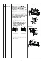
Condition to remove drain pan.
Type A: Remove
2
fixing screws of the drain pan
Type B: Can be remove from body back
Louver motor
connector
P.C.board
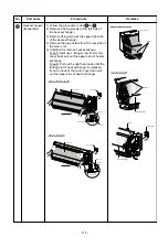
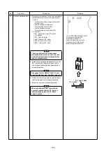
<To re-installation>
- Press the drain pan into the back body
- Please make sure ribs of drain pan in left
and right side must be install to lock position.
- Press the center arm of drain pan to back
body.
Electric part cover
Screw
Connectors
Unit display
Screw
Louver motor
connector
Type : A (For 05,07,10,13k)
Type : B (For 16,18k)
Louver motor
connector
Screw
Screw
Drain pan
Center arm
of drain pan
Back body
Drain pan
Rib of drain pan
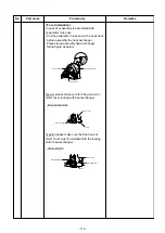
Drain pan
Back body
Back body
Type : A (For 05,07,10,13k)
- 112 -

