


No.
Part name
P
rocedure
s
Remarks
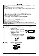
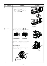
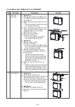
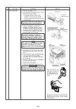
Front panel
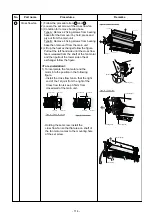
Electric part
box assembly
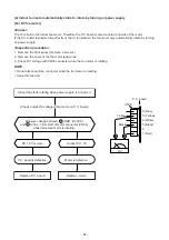
1)
Stop operation of the air conditioner and turn
off its main power supply.
2)
S
ecurely remove
two
screws at the front
panel.
Type A: Open the air inlet grille upward.
Type B: Open two screw caps.
3) Take off the hooks of front panel from top side
of the back body.
4) Slightly open the lower part of the front panel
then pull the upper part of the front panel
toward you to remove it as shown on figure.
3
4
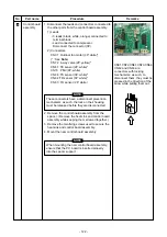
1) Follow the procedure item 3 .
2) Remove screw holding the electric part cover.
3) Disconnect the connectors for the fan motor
and louver motor from P.C. board assembly.
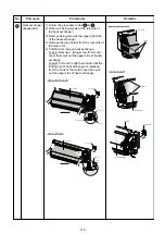
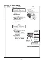
4) Remove the earth screw and earth line from
evaporator.
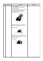
5) Pull out TC and TCJ sensor from sensor
holder of the evaporator.
6) Remove the 2 fixing screws that secures the
electric parts box assembly, unit display
assembly and remove the electric parts box
assembly.
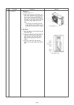
Earth screw
Earth line
Washer
TC sensor
or TCJ sensor
Sensor holder
Screw
Screw
Front panel
Front panel
Screw
Screw
Screw cap
Electric part cover
Screw
Connectors
Electric parts box
Screw
Unit display
Screw
Type : A (For 05,07,10,13k)
Type : B (For 16,18k)
Louver motor connector
Earth line
TC sensor
TA sensor
Fan motor connector
TCJ sensor
Front panel
Back body
Hooks of
front panel
- 110 -