39
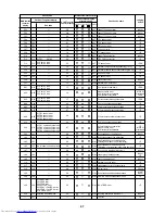
No.
15
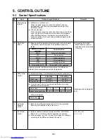
Outline of specifications
<Operation standby> .......... Display on remote controller
(1) • “P05” is one of displays of power wire missing.
• “P05” of power cable is detected.
• “COOL/DRY” operation cannot be performed because the
other indoor unit is under “HEAT” operation.
• “HEAT” operation cannot be performed because COOL
priority is set (Outdoor I/F P.C. board SW11 1-bit is ON)
and the other indoor unit is under “COOL/DRY” operation.
• “FAN” operation cannot be performed because the system
performs “Heat oil/Refrigerant recovery” operation.
• There is a unit in which indoor overflow “P10” is detected.
• There is a unit in which interlock alarm “P23” is detected.
(2) The above indoor units unavailable to operate waits under
condition of thermostat OFF.
<HEAT standby> .................. Display on remote controller
(1) • HEAT thermostat is OFF.
• During HEAT operation, the fan rotates with lower air speed
than one specified in order to prevent discharge of cold
draft or stops. (including case that defrost operation is
being performed)
• “HEAT” operation cannot be performed because COOL
priority is set (Outdoor I/F P.C. board SW11 bit 1 is ON) and
the other indoor unit is under “COOL/DRY” operation.
(2) “HEAT standby” is displayed until the above conditions are
released.
Remarks
• “
” goes on.
Item
“
” and “
”
display
(Operation and
heating stand-by)
• “
” goes on.
16
Selection of
central control
mode
(1) The contents which can be changed on the remote controller
at indoor unit side can be selected by setup at the central
controller side.
(2) In case of operation from TCC-LINK central controller
(TCB-SC642TLE, etc.)
[Central control mode 1] : Cannot operate
[Central control mode 2] :
Cannot operate, stop, select mode, set up temp.
[Central control mode 3] :
Cannot select mode, set up temp.
[Central control mode 4] : Cannot select mode
(3) RBC-AMT21E (Wired remote controller)
While mode is the central control mode, “
CENTRAL”
lights on the display part of the remote controller.
If operation is performed
from the remote control
“CENTRAL CONTROL”
mode, the status is
notified with receiving
sound.
Summary of Contents for MMU-AP0152SH
Page 20: ......
Page 21: ......
Page 22: ......
Page 23: ......
Page 24: ......
Page 25: ......
Page 26: ......
Page 27: ......
Page 28: ......
Page 29: ......
Page 30: ......
Page 31: ......
Page 32: ......
Page 33: ......
Page 34: ......
Page 53: ......
Page 54: ......
Page 55: ......
Page 56: ......
Page 57: ......
Page 58: ......
Page 59: ......
Page 60: ......
Page 61: ......
Page 62: ......
Page 63: ......
Page 64: ......
Page 65: ......
Page 67: ......
Page 68: ......
Page 69: ......
Page 70: ......
Page 71: ......
Page 72: ......
Page 73: ......
Page 74: ......
Page 75: ......
Page 76: ......
Page 77: ......
Page 78: ......
Page 79: ......
Page 80: ......
Page 81: ......
Page 82: ......
Page 83: ......
Page 84: ......
Page 85: ......
Page 86: ......
Page 87: ......
Page 88: ......
Page 89: ......
Page 90: ......
Page 91: ......


