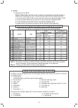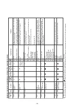
No.
17
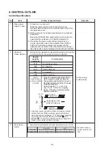
Item
Display of
[READY]
[HEAT READY]
Outline of specifications
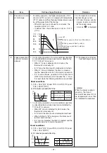
< READY>
Displayed on the remote controller
1) When the following check codes are indicated
• Open phase of power supply wiring [P05] was detected.
• There is an indoor unit that detected the indoor overflow
[P10].
• There is an indoor unit that detected the interlock alarm
[L30].
2) During Force Thermostat-OFF
• [COOL/DRY] operation is unavailable because the other
indoor unit operates with [HEAT] mode.
• [HEAT] operation is unavailable because COOL priority
(SW11-bit1 of the Outdoor I/F P. C. board is ON) is set and
the other indoor unit operates with [COOL/DRY] mode.
3) The above indoor units that cannot operate stay in
Thermostat-OFF status.
4) The indoor fan stops because the system performs
[Recovery operation for heating refrigerant (Oil)].
<HEAT READY>
Displayed on the remote controller
The indoor fan stops in order to prevent discharge of cool air
when heating operation started or during heating operation.
(including the defrost operation during thermostat-OFF)
1) Selection of the contents that can be operated by the
remote controller at the indoor unit side is possible
according to setting at the central controller side.
2) Setting contents
Remarks
•
< READY >
display
No display for wireless
type remote controller
•
<HEAT READY >
display
(
: Operation possible
: Operation impossible)
Selection of
central control
mode
18
Operation from
central controller
Individual
[Central 1]
[Central 2]
[Central 3]
[Central 4]
Operation on remote controller
ON/OFF
Operation
Timer
Temp.
Fan speed
Air direction
setting
selection
setting
setting
setting
setting
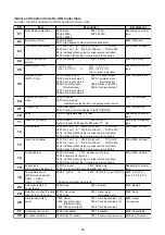
Display of filter
sign [
]
(Not provided to
the wireless
type)
1) The filter sign is displayed with LC by sending the filter-
reset signal to the remote controller when the specified
time (150H/2500H) elapsed as a result of integration of the
operation time of the indoor fan.
2) The integrated timer is cleared when the filter-reset signal is
received from the remote controller.
In this time, if the specified time elapsed, the counted time is
reset and the liquid crystal display is deleted.
16
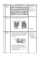
Alarm output
setup
DN
Alarm output of the
header indoor unit
Setting data
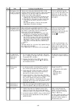
The alarm output from the indoor P.C. board is output in each
indoor unit during group control, but it can be set so as to be
output in the header unit and follower units.
Following the table below, register the setting data in DN Code "79".
Connector CN61
(Refer to
8-3-1,8-3-2. Optional
connector specifications of
indoor P.C.board
(MCC-1643
Be
sure to change the setting
data while operation
stops.
15
79
Not including the state of follower units
0000 (Factory default)
Including the state of follower units
0001
- 23 -


