background image

Management Software

Advanced Settings

  231

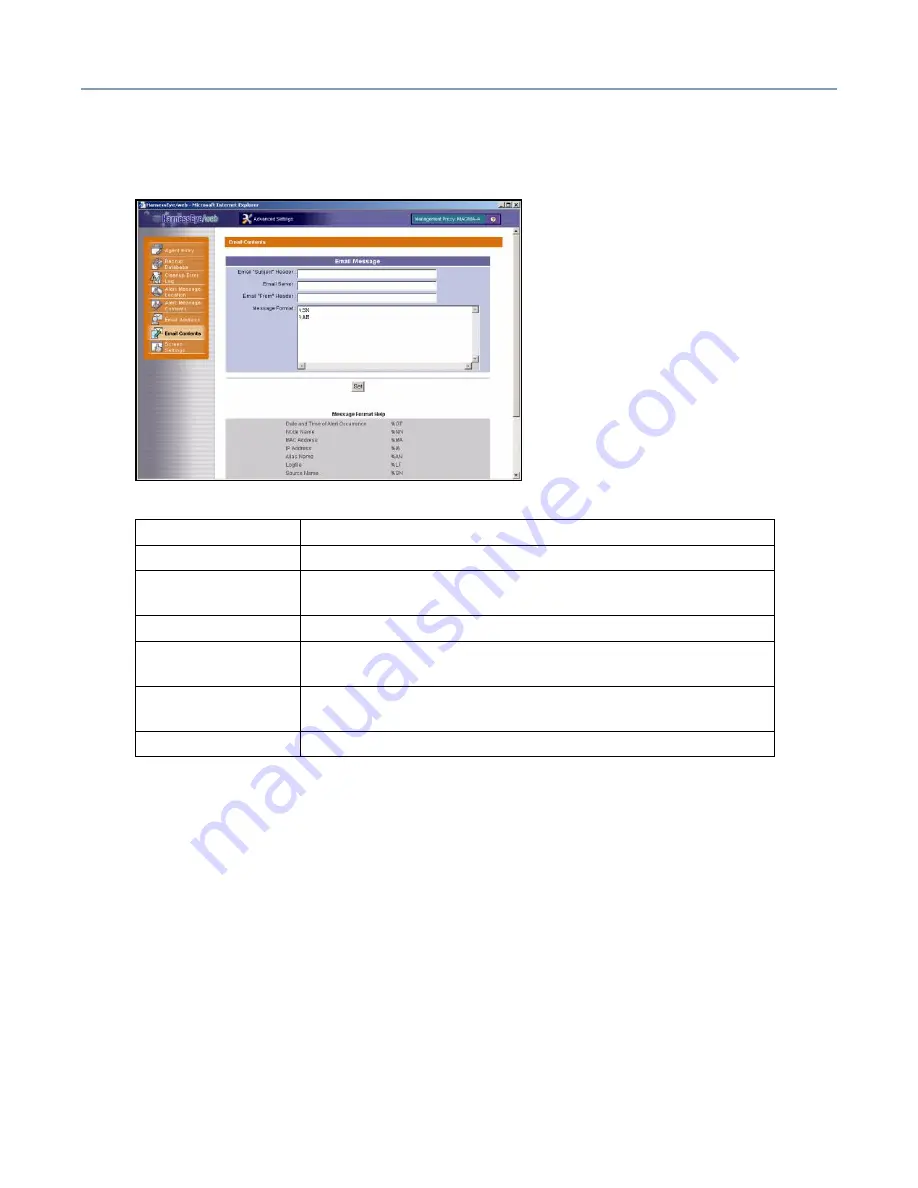
Email Contents screen

When you select 

Email Contents

, the following screen displays. 

Item

Explanation

Email Message

You can design the e-mail message headers and text.

Email “Subject” 
Header

Specify the e-mail Subject line.

Email Server

Specify the SMTP server name.

Email “From” 
Header

Specify the e-mail “From” address.

Message Format

Specify the message text using desired character strings in 
combination with command arguments explained below.

Set

Saves the E-Mail Contents settings.

Summary of Contents for Magnia 3310

Page 1: ......

Page 2: ...the latest drivers view detailed installation instructions and access the latest server information Toshiba Global Support Centre Calling within the United States 800 457 7777 Calling from outside the United States 949 859 4273 For troubleshooting information see If Something Goes Wrong on page 245 SV149 0703M1 TOSHIBA ...

Page 3: ... port USB port and monitor port Changes or modifications made to this equipment not expressly approved by Toshiba or parties authorized by Toshiba could void the user s authority to operate the equipment TOSHIBA EU Declaration of Conformity EU Übereinstimmungserklärung Déclaration de conformité UE Declaración de conformidad de la UE Dichiarazione di conformità UE EU Försäkran om Överensstämmelse T...

Page 4: ... der EMC Richtlinie 89 336 EG Informations complémentaires Ce produit est conforme aux exigences de la directive sur les basses tensions 73 23 CEE et de la directive EMC 89 336 CEE Información complementaria El Producto cumple los requisitos de baja tensión de la Directiva 73 23 CEE y la Directiva EMC 89 336 CEE Ulteriori informazioni Il prodotto é conforme ai requisiti della direttiva sulla bassa...

Page 5: ...ved Under the copyright laws this guide cannot be reproduced in any form without the prior written permission of Toshiba No patent liability is assumed however with respect to the use of the information contained herein 2003 by Toshiba America Information Systems Inc All rights reserved This appliance contains a laser system and is classified as a CLASS 1 LASER PRODUCT To use this model properly r...

Page 6: ...ORS OR OMISSIONS CONTAINED HEREIN IN NO EVENT SHALL TOSHIBA BE LIABLE FOR ANY INCIDENTAL CONSEQUENTIAL SPECIAL OR EXEMPLARY DAMAGES WHETHER BASED ON TORT CONTRACT OR OTHERWISE ARISING OUT OF OR IN CONNECTION WITH THIS MANUAL OR ANY OTHER INFORMATION CONTAINED HEREIN OR THE USE THEREOF Some states do not allow the exclusion of incidental or consequential damages so the above limitation or exclusion...

Page 7: ...arted 20 Make sure you have everything 20 Installing optional internal devices 20 Environmental considerations 20 General environmental considerations 20 Power requirements 23 Front of the server 23 Limiting access to server controls 24 Server controls indicators and drives 25 Removing and replacing the server panels 30 Removing the side panel pedestal model 30 Replacing the side panel pedestal mo...

Page 8: ...disk drive 44 Starting the server from the hard disk drive 45 Starting the server from the CD ROM drive 45 BIOS setup 46 Setting the system configuration 46 BIOS Setup Utility 46 Onboard SCSI Utility 46 Turning off the server 46 Performing a normal shutdown 46 Performing an abnormal system shutdown 47 Chapter 2 Connecting Hardware Devices 48 Installing optional devices 48 Before you start 48 Maint...

Page 9: ...ices 87 Removing device bay spacers 87 Installing SCSI devices 88 Removing SCSI devices 90 Hard disk drives HDDs 91 Downgraded server operation 91 RAID failures 93 Installing a hard disk drive 93 Replacing a hard disk drive 95 Expansion cards 97 Restrictions on PCI expansion cards 98 Setting IRQ levels 98 Cautions when adding RAID controllers and SCSI host adapters 98 Installing expansion cards 98...

Page 10: ...uration 123 Simplified RAID Configuration Setup 124 Operating System Installation 125 Windows 2003 Quick Installation 126 Windows 2000 Quick Installation 139 Windows 2003 Manual Installation using SST 154 Windows 2000 Manual Installation using SST 156 Windows 2003 2000 Manual Installation without SST 158 Post Installation Windows Server 2003 159 Post Installation Windows 2000 160 Additional Softwa...

Page 11: ...nessEye web 174 Removing HarnessEye web 180 Using HarnessEye web 181 Initial Screen 181 Agent List screen 183 Remote Console screen 184 Main Summary screen 185 Details screen 187 Product Information screen 189 Sensor Status screen 190 IDE RAID Status screen 192 SCSI RAID Status screen 194 Mobile IP Software screen 196 Software Access Point screen 200 Error Log 201 Remote Power Control screen 202 C...

Page 12: ...Agent Information Add Delete Tool 234 Starting the tool 234 Using the tool 234 Management Proxy Add Delete Tool 235 Starting the tool 235 Using the Tool 235 Alert Message Function 236 Starting the Function 236 Using the Function 236 Local Configuration Tool 239 Starting the tool 239 Using the tool 239 Remote Management 242 Connection from the Guest 243 Verifying Connection on the Guest Side 244 Ve...

Page 13: ... midway 250 Cannot install the OS 250 The OS does not boot or the OS bootup stops midway 251 Windows 2000 is locked or cannot be used 251 The power button does not function after a system abort 251 Remedy when Windows 2000 is Usable 252 Remedy when Windows 2000 is Unusable 252 Abnormal system shutdown 253 Before calling for service 253 Toshiba Technical Support 253 Chapter 7 Hardware Diagnostics 2...

Page 14: ... functions Pedestal models quickly and easily convert to 5U rack mount with a rack mount kit Supports up to six 146 GB SCSI hot swappable RAID ready SCA drives Single channel 64 bit Ultra 320 SCSI PCI RAID controller option Three 5 25 inch device bays one occupied by the CD ROM drive Redundant power supply capable Easy to upgrade memory modules and expansion cards no tools needed Split front panel...

Page 15: ...ons All safety instructions must be read carefully and fully understood before attempting to use your Toshiba Magnia 3310 3310R server This guide contains the safety instructions that must be observed in order to avoid personal injury or damage to your server The safety instructions have been classified according to the seriousness of the risk and the following icons highlight these instructions a...

Page 16: ...caution labels CD ROM caution label EPS R cage Warning and Danger labels A warning label is attached to the power supply units of this equipment as shown below Provides important information TECHNICAL NOTE This icon highlights technical information about the server HINT This icon denotes helpful hints and tips DEFINITION This icon indicates the definition of a term used in the text CLASS 1 LASER P...

Page 17: ...rior case is dirty or stained clean it with a soft cloth If necessary moisten the cloth with water Never use harsh chemicals to clean the server Setting up your work environment You can work more comfortably and efficiently by thoughtfully organizing your work space Developing good work habits is the best way to avoid strain and stress to your hands back neck and eyes Never remove the caution labe...

Page 18: ...mputer and desktop tools can help you avoid stress related injuries and make working more efficient Adjusting the lighting can make it easier to see your work and reduce eye strain Place the keyboard on a flat surface directly in front of you at a comfortable distance When you use the keyboard your arms and hands should be in a relaxed position with your forearms parallel to the floor You should b...

Page 19: ... supports the lower curve of your spine If necessary use a cushion to provide extra back support Sit with your back straight so that your knees hips and elbows form approximately 90 degree angles when you work Do not slump forward or lean back too far Using your arms and wrists Keep your wrists straight while typing If necessary adjust the keyboard and chair height to keep wrists straight Avoid re...

Page 20: ... knowledge and experience If you have no experience installing and removing computer hardware devices or if the job seems difficult consult an authorized Toshiba Magnia service provider Toshiba assumes no liability for damages if you install and remove optional devices yourself Environmental considerations This section lists precautionary measures to take when setting up pedestal and rack mounted ...

Page 21: ... power cable from the AC outlet Do not turn the server back on Contact an authorized Toshiba Magnia service provider immediately Only operate the server under the following temperature and humidity conditions Ambient temperature Pedestal model 50 F to 95 F 10 C to 35 C Rack model 50 F to 89 F 10 C to 32 C Relative humidity 30 to 80 Rh no condensation To avoid damage from condensation when the room...

Page 22: ...ls In addition to the general environmental considerations keep in mind these additional points Use only the rack and rack mount kit specified by Toshiba to install a rack model The equipment rack must provide sufficient airflow to the server to maintain proper cooling Allow 24 inches 60 cm of clearance in front and behind the rack Installing a Toshiba Magnia 3310 3310R in a rack requires special ...

Page 23: ... of power to the server Toshiba recommends the use of an uninterruptible power supply UPS If you have questions about the wiring of your AC power source consult an authorized electrician Front of the server Upper door The upper door allows access to the indicators switches device bay CD ROM drive and floppy disk drive Front door panel The front door panel allows access to the hard disk drives and ...

Page 24: ...anel controls and internal components To prohibit server access close the upper and lower front doors insert the key into the door lock and turn it to the No Access position Limited access Opening the upper door allows access to the power button reset button device bay CD ROM drive and floppy disk drive To permit access only to these items close the lower door panel insert the security key into th...

Page 25: ...tors and drives Toshiba Magnia 3310 pedestal Toshiba Magnia 3310R rack Front door lower HDD status indicator System status indicators Floppy disk drive Side panel lock Removable door hinge Front door upper CD ROM drive Hard disk drive Device bay Operation buttons ...

Page 26: ...de the user must have shutdown rights To reactivate the power button enter your user or administrator password For more information on security mode see Security menu on page 111 To avoid data loss or corruption never use the Reset button while the activity indicator on the floppy disk drive CD ROM drive or hard disk drive s is on TECHNICAL NOTE The procedure for shutting down the server depends o...

Page 27: ... RAID controller is in use Amber Disk failure has occurred valid only when the RAID controller is in use Flashing green Disk drive in operation For models without a RAID controller this indicator also flashes when another SCSI device connected to the on board SCSI controller is running Fan Fault Off Indicates one of the following Out of operation Cooling fan is operating normally Amber The Cooling...

Page 28: ...per clip through the pinhole and press gently Volume control dial Use to adjust the audio output level of the server Activity indicator Illuminates when the CD ROM is being accessed HINT The CD ROM drive has a disc tray equipped with retainers to hold the CD in place on the tray It is only necessary to use these retainers if the server is mounted in a rack To avoid damaging the CD ROM drive when m...

Page 29: ...tes whenever the floppy disk drive reads or writes data Eject button Releases the diskette from the drive To avoid damaging the CD ROM drive never press the eject button while the status indicator is on To avoid losing or corrupting data stored on the diskette never press the eject button while the FDD activity indicator is on Remove the diskette from the floppy disk drive whenever the drive is no...

Page 30: ... front panel To install optional devices inside the server you need to remove the side panel if your server is a pedestal model or the top panel if your server is a rack model Removing the side panel pedestal model To remove the side panel 1 Shut down the server turn off the power and unplug the power cable 2 Turn the side panel lock counter clockwise to release it Releasing the side panel lock Wh...

Page 31: ...l onto the server 2 Turn the side panel lock to the locking position 3 Make sure all panels are locked then close the front doors 4 Plug in the power cable cables if you have a redundant power supply Removing the top panel rack models Follow these steps to remove the top panel 1 Shut down the server turn off the power and unplug the power cable 2 Unplug the display cable keyboard cable and others ...

Page 32: ...panel lock to release the lock 6 Slide the top panel towards the rear of the server to remove it Replacing the top panel rack models Follow these steps to replace the top panel 1 Carefully slide the top panel onto the server 2 Turn the side panel lock to the locking position 3 Press the rail latches inward to release the server from its locked position then slide the server into the rack 4 Tighten...

Page 33: ...a 3310 3310R servers have two EPS R power supply modules providing the server with power supply redundancy and load sharing capabilities AC receptacle I O Expansion connectors slots Standard EPS R module Redundant EPS R module AC receptacle Power supply release push down to release Power supply release push down to release ...

Page 34: ...regulate the temperature inside the server the Toshiba Magnia 3310 3310R is equipped with Intake fan module s For redundancy up to two intake fan modules can be installed in tandem in the fan bays located in the forward lower section of the server chassis Exhaust fan module s The exhaust fan module duct contains a single fan but can be fitted with an additional exhaust fan module for redundancy EP...

Page 35: ...any cooling fan fails If one of the redundant cooling fans fails the server can be kept running in downgraded operation If two or more modules fail the server must be shut down immediately Exhaust fan The exhaust fan module comprises the primary exhaust fan and the exhaust duct Standard and redundant fans operate at all times during regular operation A CPU fan is attached to the 3 06 GHz CPU modul...

Page 36: ...atus indicators The Toshiba Magnia 3310 3310R server can accommodate up to 6 hard disk drives The status of each hard disk drive is indicated by both a DC power indicator and a status indicator under each drive bay When the status indicator is amber and your system has a built in RAID controller the corresponding hard disk drive may be faulty If the drive is defective replace it For more informati...

Page 37: ...s TECHNICAL NOTE The output voltages from the I O connectors on the back of the server do not exceed 12V Icon Description PS 2 Keyboard connector PS 2 Mouse connector Parallel printer connector RGB display connector Serial 1 connector Keyboard connector RGB connector Ether1 connector connector Serial 2 connector Parallel Mouse connector USB 1 connector USB 2 connector Ether2 connector Ether1 Ether...

Page 38: ...tion status indicator ACT Flashing green Data being transferred Off No connection Link communication status indicator LINK Green Connected but waiting Off Not operating Ether1 Link 1000 100 Mbps indicator Green 1000 Mbps Yellow 100 Mbps Ether2 Link 100 10 Mbps indicator Green 100 or 10 Mbps Serial 1 connector used to connect an RS 232C compliant device USB ports 1 and 2 When connecting a USB devic...

Page 39: ... all connected peripheral devices are turned off and that their power cables are not plugged into an AC outlet 2 Using the proper interface cable connect each peripheral device to an appropriate connector on the server If the plug on the interface cable has thumbscrews tighten the thumbscrews sufficiently to secure the cable Connecting peripheral devices 3 Tighten any connector screws 4 Plug the p...

Page 40: ... such as an air conditioner or photocopier To connect the server to an AC power source 1 Plug the power cable s into the connector on the back of the server Securing the power cable 2 Plug the power cable into an AC outlet or preferably the power output connector of an uninterruptible power supply UPS Handling the cord on this product will expose you to lead a chemical known to the State of Califo...

Page 41: ...failure condition Replace or repair the failed cooling fan as soon as possible Prolonged downgraded operation could shorten the service life of each system component If the remaining cooling fan fails important data and programs could be corrupted or lost For more information on fault indications see System indicators on page 27 When a 3 06 GHz CPU module is installed the exhaust fan duct is not r...

Page 42: ...es in the server For information on upgrading system memory see Memory modules on page 60 Expansion slots The motherboard has six PCI expansion slots two 64 bit 100 MHz slots two 64 bit 66 MHz slots and two 32 bit 33MHz slots Turning on the server 1 Check that all the peripheral devices such as the monitor keyboard and mouse are properly connected to the server 2 Check that all power cables are co...

Page 43: ...ect Control Panel Hardware then Device Manager 2 Within the Network Adapters Intel R 82545EM Based Network Connection Properties from the Details tab 3 Set Enable PME to Enabled and set Wake on Settings to Wake on Magic Packet then select OK 4 Select the Network Adapters Antler 82545EM Based Network Connection Properties Power Management Tab 5 Set both the Allow this device to check box and Allow ...

Page 44: ...OST a message similar to the following appears on the screen Pressing the F2 key starts the BIOS setup utility If you do not press F2 system startup continues If an error is detected by the POST depending on the error condition one of the following occurs A beep sounds during testing An error code and message appear after the POST completes Booting the server You can boot the server from any of th...

Page 45: ... the boot sequence 5 Press F10 then Enter to exit the BIOS setup When you press F10 any changes are saved and the system restarts 6 Immediately press the CD ROM drive s eject button and insert the CD ROM for booting the OS If a bootable CD is loaded in the CD ROM drive and it is recognized by the system the server will not recognize the hard disk drive as a boot device even if you eject the CD Pre...

Page 46: ...after shipment you may need to reconfigure the server For detailed information on configuring the server see Chapter 3 System Configuration Setup on page 106 BIOS Setup Utility In addition to the Magnia 3310 3310R Software and Documentation CD the BIOS Setup Utility allows you to configure the hardware installed in the server Onboard SCSI Utility The Onboard SCSI Utility allows you to configure th...

Page 47: ... shutdown the shutdown routine can be stopped by performing an abnormal system shutdown Initiating an abnormal system shutdown causes all unsaved data in open files to be lost To initiate an abnormal system shutdown press the reset button and power button simultaneously Using the power switch to shutdown an ACPI compliant system causes any running application software to abort before completing th...

Page 48: ...ledge and experience If you have no experience installing removing optional devices or if the job seems difficult please consult an authorized Toshiba Magnia service provider Toshiba assumes no liability for damages if you install and or remove optional devices yourself Never handle any electrical component that is not described in this manual Some parts carry high voltages and are dangerous To av...

Page 49: ...e steps in each procedure in the order written Before disconnecting any cables note their positions to make sure you can reconnect them correctly Check cable connectors for broken or bent pins If a cable connector has screws tighten the screws when securing the cable If a failure occurs consult your authorized Toshiba Magnia service provider Internal server components can be seriously damaged by s...

Page 50: ...els see Removing the top panel rack models on page 31 5 Perform the required maintenance 6 Reinstall the server s access panel For pedestal models see Replacing the side panel pedestal model on page 31 For rack models see Replacing the top panel rack models on page 32 7 Reconnect all signal cables 8 Plug the power cable into an AC outlet 9 Press the power button to turn on the server then run any ...

Page 51: ...m the rack Such a load may damage the rack s rails or cause the rack to become unstable Never lean objects against the rack and do not lean against it The rack may become unstable and cause serious injury When working at high locations around the rack never lean ladders directly against the rack or against units installed in the rack The installed units may be damaged or the rack may become unstab...

Page 52: ...om its locked position then slide the server into the rack 2 Tighten the two thumbscrews on the front panel to secure the server to the rack 3 Reconnect any cables that were disconnected from the server Toshiba supplied hardware items The following table lists the hardware items that Toshiba provides with your server Type Usage Screw A metric Installing units except HDDs or DAT on the drive carrie...

Page 53: ... increase system reliability secondary intake and exhaust fans can be installed allowing you to create a redundant cooling configuration The primary intake fan module and the primary exhaust fan module comprise the primary fan configuration for this server while the secondary intake fan module and secondary exhaust fan module comprise the redundant fan configuration Removing and installing an inta...

Page 54: ...peration shut it down Then remove the access panel For detailed instructions read Steps 1 through 4 in Maintenance overview on page 50 2 If installing a redundant fan remove the screw securing the cover plate to the fan bay then remove the cover plate there is no cover plate when installing a replacement fan Removing the fan cover plate redundant fan only 3 Position the intake fan module in the fa...

Page 55: ...n the motherboard If you are installing a secondary intake fan module attach the fan cables to the J5 FAN 3 R connector on the motherboard Fan connectors on the motherboard 5 Reinstall the access panel reconnect all signal and power cables then turn on the server For instructions read Steps 6 through 9 in Maintenance overview on page 50 FAN 2R side of motherboard Redundant intake fan module side J...

Page 56: ...ise the server will overheat and may be damaged If the server is in operation shut it down then remove the access panel For detailed instructions read Steps 1 through 4 in Maintenance overview on page 50 1 Disconnect the exhaust fan module cable from the motherboard If the exhaust fan module has a redundant exhaust fan installed also disconnect the redundant fan cable from the motherboard Disconne...

Page 57: ...ust fan module cover to the server chassis and remove the cover If you are replacing an existing fan skip this step and go to Step 3 Removing the exhaust fan module cover 3 While lifting up on the exhaust fan module eject lever pull the fan module from the server Removing the exhaust fan module Exhaust fan module eject lever ...

Page 58: ...ule in the server until the eject lever for the exhaust fan module clicks to indicate a locked position Installing the exhaust fan module 6 Connect the primary exhaust fan cable to the J49 FAN 1 connector and the redundant fan cable to the J51 FAN 1 R connector To avoid server damage due to overheating never connect the exhaust fan module cable to the redundant exhaust fan connector on the motherb...

Page 59: ...nnecting the exhaust fan s Fan connectors on the motherboard 7 Reinstall the access panel reconnect all signal and power cables then turn on the server For instructions read Steps 6 through 9 in Maintenance overview on page 50 J51 FAN 1 R J49 FAN 1 ...

Page 60: ...the table below for valid module combinations Bank 1 Bank 2 Bank 3 Slot 1B Slot 1A Slot 2B Slot 2A Slot 3B Slot 3A Total Capacity 1024 1024 1024 1024 1024 1024 6144 1024 1024 1024 1024 4096 1024 1024 2048 512 512 1024 1024 1024 1024 5120 512 512 1024 1024 3072 512 512 512 512 1024 1024 4096 512 512 512 512 512 512 3072 512 512 512 512 2048 512 512 1024 256 256 1024 1024 1024 1024 4608 256 256 1024...

Page 61: ...ure to observe this precaution could result in electric shock cause a system fault or void your warranty Never install or remove memory modules immediately after turning off the server To avoid burn injuries wait for the heat around the memory modules to dissipate Installing a memory module while the server is on could cause damage to the server or the memory module Memory modules can be seriously...

Page 62: ...e rear of the server and pull it from the server Removing the exhaust fan duct fan duct not installed on all models 4 Remove any expansion cards that might be installed See Removing expansion cards on page 100 for more information When a 3 06 GHz CPU is installed the exhaust fan duct is not attached and Steps 2 and 3 are not required When removing expansion cards make a note of which slot they cam...

Page 63: ...aust fan unit counterclockwise to release the module Be sure to support the exhaust fan unit with your hands to prevent the fan unit from dropping while you are loosening the screws Releasing the lock of the exhaust fan unit 7 Remove the exhaust fan unit Be sure to support the exhaust fan unit with your hands to prevent the fan unit from dropping Removing the exhaust fan unit ...

Page 64: ...on both sides Installing a memory module 9 Attach the exhaust fan unit so that the exhaust fan unit is aligned with the two positioning pins on the enclosure and secure it with a screw Be sure to turn the screws while holding the fan unit with your hands to prevent the exhaust fan unit from falling Attaching the exhaust fan unit Installing a memory module the wrong way could damage the memory modu...

Page 65: ...1 R on the motherboard Attaching the exhaust fan cables 11 If expansion cards have been removed install them according to the procedure See Installing expansion cards on page 98 for more information 12 Insert the exhaust fan duct and attach it in the server by sliding it toward the front of the server Attaching the exhaust fan duct fan duct not installed on all models When a 3 06 GHz CPU is instal...

Page 66: ...press the levers securing the memory module away from the module then lift the memory module from the connector Removing a memory module Removing a memory module while the server is on could cause damage to the server or the memory module Memory modules can be seriously damaged by static electricity Wear a wrist or heel ground cable to discharge static electricity carried on your body If such equi...

Page 67: ...aust fan unit so that the exhaust fan unit is aligned with the two positioning pins on the enclosure and secure it with a screw Be sure to turn the screws while holding the fan unit with your hands to prevent the exhaust fan unit from falling Attaching the exhaust fan unit 5 Attach the cable from the exhaust fan unit that you attached to the motherboard Connect the standard exhaust fan module to J...

Page 68: ...ching the exhaust fan duct fan duct not installed on all models 8 Lock the exhaust fan duct by turning the screw clockwise Locking the exhaust fan duct fan duct not installed on all models 9 Replace the memory slot cover if available 10 Reinstall the access panel reconnect all signal and power cables then turn on the server For instructions read Steps 6 through 9 in Maintenance overview on page 50...

Page 69: ...or technology For example if you wish to upgrade a Toshiba Magnia 3310 3310R server configured with a single 2 40 GHz 512 KB L2 cache CPU module to a dual CPU configuration you would install an additional 2 40 GHz 512 KB L2 cache CPU module Continuing this example if you were upgrading the server to run dual 3 06 GHz CPU modules you would need to replace the CPU shipped with the server with a 3 06...

Page 70: ...nty Never install or remove CPU modules immediately after turning off the server To avoid burn injuries wait for the heat around the CPU modules to dissipate Installing a CPU module while the server is on could cause damage to the server or the CPU module CPU modules can be seriously damaged by static electricity Wear a wrist or heel ground cable to discharge static electricity carried on your bod...

Page 71: ... Replacing the Retention Clamp When you add a 3 06GHz CPU module or replace a 2 40 GHz CPU module with a 3 06 GHz module use the following procedure to replace the retention clamps 1 Push down the retention clamp lever of the left side and then turn and remove the screws Turning and removing screws 2 Use the screws to attach the retention clamp that comes with the 3 06 GHz CPU Attaching the retent...

Page 72: ...unlock the heat sink Removing the heat sink 2 Remove the heat sink 3 Raise the CPU lock levers of the CPU socket in which the CPU module you want to move is installed Do not replace both left and right retention clamps at the same time The plates attached to the backside of the board for securing the retention clamps and the screw holes on the retention clamps may be displaced Always replace only ...

Page 73: ...Raising the CPU lock lever 4 Remove the CPU module Removing the CPU module For a 3 06 GHz CPU module 1 Disconnect the fan cable from the fan connector J6 for CPU1 and J7 for CPU2 Disconnecting the fan cable CPU1 Disconnecting the fan cable CPU2 ...

Page 74: ...k lock levers 3 In the same way lift and release the right heat sink lock lever 4 While lightly pressing toward the inside of the retention clamp remove the claws at both ends of the fan from the holes to the left and right of the retention clamp Removing the heat sink claws Do not pinch your fingers during the procedure ...

Page 75: ...U lock levers of the CPU socket in which the CPU module you want to remove is installed Raising the CPU lock lever 7 Remove the CPU module Removing the CPU module Contact your Toshiba service station or sales representative if you have problems removing a heat sink Services will be provided for a fee Forcibly removing a heat sink may damage the CPU or CPU socket ...

Page 76: ...he expansion CPU socket Raising the CPU lock lever A standard CPU module is installed in CPU socket 1 To add a CPU module install it in CPU socket 2 Before you install a CPU into a CPU socket make sure that the lever of the CPU socket is fully opened about 135 degrees If you insert the CPU without opening the lever of the CPU socket completely it will not only cause the recognition failure of the ...

Page 77: ...the CPU should fall into place without requiring any force on your part Press in the CPU module until both ends are even and flat It should not require much if any manual assistance Inserting the CPU module 4 Push down the socket lock lever until it hooks on the socket claw and is locked in place Pushing down the CPU lock lever A standard CPU module is installed in CPU socket 1 To add a secondary ...

Page 78: ...to the heat sink need to be replaced When the CPU module is initially added while in default status When a 2 40 GHz CPU module is removed and changed to a 3 06 GHz CPU module Refer to Replacing the Retention Clamp on page 71 for details Installing and Removing Hardware 1 Connect the fan cable of the new heat sink to the fan connector J6 for CPU1 and J7 for CPU2 Do not push the fin section of heat ...

Page 79: ...ck lever Before you install a CPU into a CPU socket make sure that the lever of the CPU socket is fully opened about 135 degrees If you insert the CPU without opening the lever of the CPU socket completely it will not only cause the recognition failure of the CPU but also damage the CPU of CPU socket or generate short circuit inside the CPU socket which may require repair ...

Page 80: ...ire much if any manual assistance Inserting the CPU module 4 Push down the socket lock lever until it hooks on the socket claw and is locked in place Pushing down the CPU lock lever 5 For both CPU1 and CPU2 latch both ends of the claws of the heat sink in the left and right retention clamp holes on the power supply side of the CPU s A standard CPU module is installed in CPU socket 1 To add a secon...

Page 81: ...ing the heat sink of the expansion CPU against the CPU socket simultaneously move both the left and right heat sink lock levers right in the direction of the arrows and hook the levers onto the claws to lock the heat sink in place Do not push the fin section of heat sink of the CPU module This may cause the deformation of the heat sink Used heat sinks cannot be reattached To replace a heat sink co...

Page 82: ...aching the exhaust fan duct fan duct not installed on all models 2 Lock the exhaust fan duct by turning the screw clockwise Locking the exhaust fan duct fan duct not installed on all models 3 Reinstall the exhaust fan module For instructions see Removing and replacing a primary or redundant exhaust fan on page 56 When a 3 06 GHz CPU module is installed Steps 1 and 2 installing the exhaust fan duct...

Page 83: ...oshiba Factory CMOS settings For more information refer to BIOS settings on page 108 Phoenix BIOS 4 0 Release 6 0 Copyright 1985 2000 Phoenix Technologies Ltd All Rights Reserved PUFFIN Server BIOS Version X XX BMC firmware Revision X XX CPU 2 Xeon TM Processor 2 40 GHZ XXXK System RAM Passed XXXM Extended RAM Passed TECHNICAL NOTE If the server is running Windows you may need to reconfigure Windo...

Page 84: ...se you risk causing heat an explosion or a fire To ensure proper system operation replace the battery with one of the same type Replacing the internal battery 1 If the server is in operation shut it down Then remove the access panel For detailed instructions read Steps 1 through 4 in Maintenance overview on page 50 2 If any expansion cards are obstructing access to the battery remove the card s ac...

Page 85: ...ive electrode facing up Installing the battery 5 Reinstall any expansion cards you removed For instructions see Installing expansion cards on page 98 6 Reinstall the access panel reconnect all signal and power cables then turn on the server For instructions read Steps 6 through 8 in Maintenance overview on page 50 7 Set up the server according to the system configuration information that you wrote...

Page 86: ...g SCSI Devices SAF TE SAF TE communicates its status to a software agent resident in the server through the SCSI bus and then sends out an appropriate notification This notification includes Detection of device presence Status of a device bay slot SCSI device Channel A Ultra320 Wide 68 pins Channel B Ultra320 Wide 68 pins SCSI controller 7 7 SAF TE controller 6 HDD 0 5 TECHNICAL NOTE Optional SCSI...

Page 87: ...tructions read Steps 1 through 4 in Maintenance overview on page 50 2 Press the rail latches inward then remove the spacer from the device bay Removing the device bay spacer 3 Remove the rails attached to the device bay spacer You will need these rails to install a SCSI device in the 5 25 inch device bay When installing Windows 2000 using the Server Setup Tool with a hard disk drive connected to t...

Page 88: ...ps 1 through 4 in Maintenance overview on page 50 2 Remove the device bay spacer For instructions see Removing device bay spacers on page 87 3 Remove the rails attached to the device bay spacer Removing the rails from the device bay spacer Installing a SCSI device while the power is on may damage the server and the SCSI device SCSI devices can be seriously damaged by static electricity Wear a wris...

Page 89: ...evice 5 Partially position the device in the empty device bay slot and then connect the power and signal cables Connecting the power and signal cables HINT There are three types of predrilled holes on each rail In most cases you will use the round holes when attaching the rails to a SCSI device Verify pin locations using the device s documentation manual ...

Page 90: ...ices 1 If the server is in operation shut it down Then remove the access panel For detailed instructions read Steps 1 through 4 in Maintenance overview on page 50 2 Depress the rail latches located on both sides of the SCSI device then partially slide the SCSI device out of the device bay slot 3 Disconnect the power and signal cables Disconnecting the power and signal cables 4 Remove the SCSI devi...

Page 91: ...rives HDDs The server drive carrier contains six drive bays Each bay is assigned a unique SCSI address Starting with the leftmost drive bay for rack mount models or the bottom most bay for pedestal models the SCSI IDs are assigned as follows Bay 0 SCSI ID 0 Bay 1 SCSI ID 1 Bay 2 SCSI ID 2 Bay 3 SCSI ID 3 Bay 4 SCSI ID 4 Bay 5 SCSI ID 5 When adding a hard disk drive to the server always position th...

Page 92: ...one disk fails the other disk can be used to run the system and reconstruct the failed disk Since the disk is mirrored it does not matter if one on them fails because both disks contain the same data at all times Either disk can act as the operational disk This level provides 100 redundancy because each drive in the system is duplicated This type of array is used for read intensive fault tolerant ...

Page 93: ...ng hard disk drive Parity RAID configuration failure RAID 5 The data in a RAID 5 array is kept in an encoded format distributed across the number of independent drives in the array Consequently write operations on a RAID 5 array are slower than a non RAID configuration This is true even if the parity RAID is functioning normally When a hard disk drive in a parity RAID fails every other hard disk d...

Page 94: ...rive bay 5 Place the new HDD drive tray assembly in the drive bay and slide it to the rear of the bay Installing the HDD drive tray assembly 6 Close the drive bay latch applying a small amount of pressure to seat the HDD drive tray assembly into position Closing the drive bay latch 7 Close the server s upper door and lower door panel 8 Plug the power cable into an AC outlet or UPS 9 Press the powe...

Page 95: ... drive hot spare in reserve the server can run in a downgraded operational state with up to two failed hard disk drives if the RAID array has had time to rebuild from the first failure However if a third device fails important programs or data may be destroyed or lost If the server does not have a RAID controller If the server is not configured with a RAID controller check the status indicator of ...

Page 96: ...lty hard disk drive The hard disk drive partially extends from the drive bay Opening the drive bay latch 4 Wait five to ten seconds for the disk to spin down then using both hands remove the HDD drive tray assembly from the drive bay Removing the hard disk drive tray 5 Place the new HDD drive tray assembly in the drive bay then slide it to the rear of the drive cage Hard disk drives generate heat ...

Page 97: ...em checks 8 Close and lock the server s upper door and front door panel For information on limiting access to server controls see Limiting access to server controls on page 24 9 If a RAID controller is installed rebuild the disk array For information on rebuilding the disk array refer to the user s guide that came with your RAID controller Expansion cards The server supports PCI expansion cards Th...

Page 98: ...ard disk drives and other start up devices In this case use the BIOS Setup Utility to specify the hard disk drive that will boot the OS operating system Follow these steps to select the hard disk drive 1 Start BIOS Setup Utilities and select Hard Drive from the Boot menu The name of the hard disk drive or the name of the controller connected with it is displayed 2 Use the or key to change priority...

Page 99: ...ove the expansion slot cover from the slot in which the expansion card is being installed Make sure that the expansion slot you select satisfies the conditions and restrictions of the expansion card you are installing Removing the expansion slot cover 4 Insert the expansion card in the slot then lower the card support to hold the expansion card in place Inserting the expansion card 5 Reinstall the...

Page 100: ...rd in place then remove the expansion card from the slot Removing the PCI expansion card 3 Position the expansion slot cover in the slot then lower the card support to hold the cover in place Installing the expansion slot cover 4 Reinstall the access panel reconnect all signal and power cables then turn on the server For instructions read Steps 6 through 9 in Maintenance overview on page 50 Removi...

Page 101: ...Disconnect the SCSI cable from the motherboard Disconnecting the SCSI cable When replacing the cache memory backup battery be sure to install it properly Failure to install the battery properly can cause it to explode For instructions refer to Replacing the internal battery on page 84 Dispose of the spent battery as required by local ordinances or regulations Installing the RAID controller while t...

Page 102: ...nstalling a RAID card that has two internal hard disk drive connectors For more information refer to the user s guide that came with the RAID controller Connecting the SCSI cable 5 Reinstall the access panel reconnect all signal and power cables then turn on the server For instructions read Steps 6 through 9 in Maintenance overview on page 50 6 Install the RAID card s configuration software then s...

Page 103: ...e EPS R power supply units fails If a power supply fails the indicator on the faulty power unit goes out and the fault lamp located on the front of the server blinks The server reconfigures itself to support a single power supply configuration allowing you to replace hot swap the faulty power supply without shutting down the system Once you have replaced the faulty power supply the server returns ...

Page 104: ...re specific technical knowledge and experience If you have no experience of installing removing optional devices or if the job seems difficult consult your authorized service provider Toshiba assumes no liability for damages if you install and or remove optional devices yourself Use extreme caution when replacing an EPS R power supply unit while the server is in use An error during power supply re...

Page 105: ...Connecting Hardware Devices Power supply units 105 5 Press the locking lever slide the power supply unit into the EPS R cage then release the lever Installing the EPS R unit ...

Page 106: ...rt the server To start the BIOS Setup Utility press the F2 key immediately after the BIOS screen appears The message Entering Setup appears on the screen After the system completes the Power On Self Test POST the BIOS Setup Utility is loaded Phoenix BIOS 4 0 Release 6 0 Copyright 1985 2000 Phoenix Technologies Ltd All Rights Reserved PUFFIN Server BIOS Version X XX BMC firmware Revision X XX Intel...

Page 107: ...s Esc Exit Select Menu Enter Select Sub Menu F10 Safe and Exit Main Sets the system date and time and floppy disk drive parameters Advanced Sets details of hardware data such as serial port parallel port parameters Security Registers changes and deletes passwords Boot Sets the boot sequence for the devices that can be booted SysInfo Displays system configuration information Exit Exits the BIOS Set...

Page 108: ...s section describes the settings available in the various BIOS Setup Utility menus All are recommended settings Main menu System Time System Date Enter the system date and time Legacy Diskette A Do not change the setting Displays the type of floppy disk drive connected Advanced menu This section describes the advanced settings available in the various BIOS Setup Utility menus All are recommended s...

Page 109: ...O address 378 Interrupt IRQ 7 DMA channel DMA 1 Specifies the parallel port mode Mode Sets the operation mode for the serial port select ECP Floppy disk controller Enabled Specifies whether the floppy disk controller is enabled or disabled I O Device Configuration On Board Devices Installed O S Win2000 NET Boot time Diagnostic Screen Enabled Reset Configuration Data No Large Disk Access Mode DOS P...

Page 110: ...e only if you understand what will result PS 2 Mouse Select Enabled Summary Screen Specifies whether the POST summary information is enabled or disabled Select Disabled Legacy USB Support Specifies whether USB devices are recognized as Legacy devices allowing you to use a USB keyboard or mouse as a PS 2 keyboard or mouse Hyper Threading Specifies whether hyper threading will be enabled or disabled...

Page 111: ...nu This section describes the Boot options available in the BIOS Setup Utility This menu allows you to set the sequence in which the operating system searches devices for the boot files All are recommended settings Removable Devices Specifies the boot sequence for the floppy disk drive and other removable storage devices Set User Password Enter Set Supervisor Password Enter Password on Boot Enable...

Page 112: ...Manufacturer TOSHIBA Product MAGNIA3310 Version X XX Serial Number XXXXXXXXXX CPU Displays the following CPU information Boot Strap Processor Installed Speed XXX XHz Socket Name BSP Manufacturer GenuineIntel Version Intel R XEON TM Application Processor Installed Speed XXX XHz Socket Name AP Manufacturer GenuineIntel Version Intel R XEON TM CPUID XXXXXXXXXXXXXXXX L2 Cache 512 KB Memory Displays th...

Page 113: ...rmation for peripherals connected to the motherboard the information will vary depending on what is actually installed Port Connector On Board Designator J53 J57 COM 1 COM 2 J55 PS 2 Keyboard Mouse J24 Primary IDE J16 Secondary IDE J33 Floppy J54 VGA Conn J50 LAN J26 USB 1 USB 2 J52 Parallel J2 J3 SCSI Channel A B BIOS Displays the following BIOS information Basic Information ROM Size 1024 KB Vend...

Page 114: ...he BIOS Setup Utility started Except passwords Save Changes Saves changes Onboard SCSI Utility The onboard SCSI Utility is set prior to shipping Use the Utility when mounting a built in type of SCSI device in the device bay or confirming the settings Starting the SCSI Utility When the server is turned on or restarted the monitor displays the onboard SCSI BIOS initialize message shown below The dis...

Page 115: ...he 5 25 device in a standard configuration that is if no RAID controller is added SCSI Utility main menu Select the desired Channel A or B and press Enter The following menu displays Select Configure View SCSI Controller Settings to set SCSI controller settings SCSI Utility keyboard commands Esc Returns control to the previous screen mode Enter Specifies a data item Returns control to the previous...

Page 116: ...tility screen SCSI Controller ID 7 ID number of Host Adapter on this bus Reset SCSI Bus at IC Initialization Enabled Display Ctrl A Message During BIOS Enabled Extended Int 13 Translation Enabled POST Display Mode Verbose SCSI Controller Int 13 Support Enabled Domain Validation Enabled Support Removable Disks Disabled BIOS Support for Bootable CD ROM Enabled Interrupt IRQ Channel 10 I O Port Addre...

Page 117: ...Low to High 0 Max Removable Media SupporT Disabled CHS Mapping SCSI Plug and Play Mapping Spinup Delay Secs 2 Secondary Cluster Server No Termination Control Auto Device Selections MB Sec 160 MT Sec 80 Data Width 16 Scan ID Yes Scan LUNs No Disconnect Yes SCSI Time Out 10 Queue Tags On Boot Choice No Format Format Verify Verify Restore Defaults Defaults ...

Page 118: ...arting Power Console Automatic rebuilding with a hot spare If the server is configured with a hot spare standby disk you can rebuild the disk array using the hot spare even if a hard disk drive other than the hot spare is malfunctioning When the rebuild completes the status indicators on that hard disk drive will turn off To ensure that the fault alarm operates properly set Alarm Control to Enable...

Page 119: ...r Fast SCSI mode Select Enabled to configure the SCSI bus for Ultra SCSI mode Select Disabled if an extended disk unit is connected to the SCSI bus Adapter Factory Defaults Use this option to reset all setup options except the following to defaults Degraded Mode Bootup The parameters such as Write Policy and Read Policy that are written under Logical drive View Update Parameters Parameters Option ...

Page 120: ... work correctly with certain optional hardware devices for example a SCSI card If the SST does not work properly remove the optionally installed hardware device s When the SST is running do not turn off or reset the server or remove the Startup Disk or SST CD ROM The SST cannot be used to install the operating system when hard disk drives are connected to two or more disk controllers To install th...

Page 121: ...e that the CD ROM is the first boot device 4 In a moment the Input Locale screen appears Select a keyboard layout from the drop down list Input Locale screen The Input Locale screen only displays when you start the SST from the Startup Disk the first time If the keyboard layout needs to be changed create a new Startup Disk using the Utilities program Power button ...

Page 122: ...screen In a moment the Main Menu appears Main Menu SST Main Menu Setup The Setup option allows you to install and configure the RAID and operating system Utilities The Utilities option allows you to customize the installation create diskettes and manage the RAID configuration The Input Locale screen displays each time you start the SST on another system The selected keyboard layout is saved when t...

Page 123: ...y a RAID type Hot Spare option and other RAID configuration information Detailed Setup This option starts the RAID configuration utility and allows you to manually configure the array Select this option when you need to configure multiple array groups multiple RAID adapters or other advanced features Skip RAID Setup Bypasses the RAID setup The following screen appears only if a MegaRAID 320 1 card...

Page 124: ...maged operation is continued by the other HDD RAID5 three or more HDDs required Multiple HDDs are grouped and constructed as a single logical device Data and parity are recorded randomly in the grouped HDDs If one HDD is damaged operation is continued by the other HDDs Hot Spare can be used if RAID1 or RAID5 is selected Hot Spare is a spare HDD in stand by mode when one HDD is damaged the hot spar...

Page 125: ...led the Operating System Installation Selection menu appears Operating System Installation screen Install Windows 2003 Quick Installation Allows a quick installation of Windows 2003 Standard Edition or Windows 2003 Server Enterprise Edition using the Server Setup Tool s automatic installation procedure Manual Installation Allows you to perform a manual installation of Windows 2003 Standard Edition...

Page 126: ...k installation procedures Locale Settings When the Install Windows 2003 Quick Installation option is selected on the Operating System Installation screen the Locale Settings Screen displays Locale Settings screen Select a Language for your operating system from the drop down list and click Next Selecting this option will create a disk partition from 50 MB to 2 048 MB If you want to install Windows...

Page 127: ...mat Selecting this option creates a 4096 MB partition NTFS Creates the file system using the NTFS NT File System format If you enter a partition size larger than the disk can accommodate a 4096 MB partition will be created by default Input Partition Size Enter the size of the disk partition you want to create then press Enter User Information Settings After specifying the disk partition parameters...

Page 128: ...ettings the License Mode Setting screen appears License Mode Setting screen You can structure the operating system license in one of two ways Per Server Mode The server s license specifies the number of clients The number of server users should be no more than the number of client computers that can simultaneously connect to that server Per Seat Mode Each client computer seat has its own license w...

Page 129: ... resources are controlled by individual computers Select one of the following options then click Next LAN Adapter Setting After specifying the Server Role the LAN Adapter Selection screen appears This screen allows you to specify the network communication protocol for on board LAN controller LAN Adapter Selection screen Select the LAN adapter being used and then click Next To make your server a do...

Page 130: ... Default Gateway Address for the on board LAN Controller 1Gbps LAN Adapter TCP IP Protocol Setting 1 screen 1 Enter an IP Address 2 Enter a Subnet Mask 3 Enter the Default Gateway Address To have the DHCP server automatically assign the IP addresses Subnet Masks and Default Gateway to your computer select Assign an IP Address from DHCP Server 4 After making your entries click Next The LAN driver f...

Page 131: ...mary DNS Server and Secondary DNS Server fields When using DHCP you can obtain the DNS Server address automatically by selecting Obtain DNS Server address automatically If you are using the Windows Name Service WINS enter the IP address for each of the WINS Servers in the Primary WINS Server and Secondary WINS Server fields After making your entries click Next TCP IP Protocol Setting 2 After speci...

Page 132: ...mary DNS Server Address Secondary DNS Server Address Primary WINS Server Address and Secondary WINS Server Address for on board LAN Controller 100Mbps LAN adapter DNS WINS Setting 1 screen If you are using the Domain Name System DNS enter the IP address for each of the DNS Servers in the Primary DNS Server and Secondary DNS Server fields When using DHCP you can obtain the DNS Server address automa...

Page 133: ...ost Configuration Protocol DHCP This allows a temporary IP address to be automatically assigned to a host when the host is connected to the network Domain Name System DNS DNS is a service that allows Domain Names to be translated into Internet Protocol addresses A Domain Name is a meaningful and easy to use easy to remember handle for an Internet address Windows Name Service WINS This resolves the...

Page 134: ...the server a part of a domain for the first time select Create Computer Account 2 If the server has already been registered for a domain or you want to make the server a part of a workgroup click Next In this case it is not necessary to create the computer account 3 In the Administrator text box enter the name of the manager or administrator account that has permission to add computers to the spec...

Page 135: ... SCSI RAID controller if the MegaRAID 320 1 controller is not installed this item will be unavailable for selection On board 1Gbps LAN Driver Ether1 Driver for the onboard 1Gbps LAN controller On board 100Mbps LAN Driver Ether2 Driver for the onboard 100Mbps LAN controller Select an option A list of devices displays Select the device you want to install Drivers are located on the SST CD ROM If you...

Page 136: ...RAID 320 1 only The SCSI MegaRAID Controller utility this option can be selected only if the MegaRAID 320 1 is installed Power Console Monitors the RAID configuration Service Extracts log information SNMP Agent Used by TCP IP based management applications To install each application automatically select the Install option To install each application driver from diskette or CD ROM select the From F...

Page 137: ...Enter the name or the IP address of the Management Proxy Server to which the Agent is registered Alias If you want to assign an alias to the Agent enter it An Alias may make it easier to specify the node name Consistency Check If you selected the SCSI RAID Utility option and are running Windows 2003 the Consistency Schedule screen displays Consistency Schedule screen Start time Select the integrit...

Page 138: ...D ROM and diskette Start installation according to parameter settings at boot time The next time the SST starts installation begins automatically after a confirmation message using the configuration information stored on the Startup Disk If the necessary devices have not yet been installed their device drivers will not be installed If this option is not selected the SST starts normally at the Main...

Page 139: ...n To change a setting highlight the item and click Jump The setup wizard will return to that screen and allow you to make changes When the installation settings are correct click Execute Windows 2000 Quick Installation This section reviews the Windows 2000 quick installation procedures Locale Settings When the Install Windows 2000 Quick Installation option is selected on the Operating System Insta...

Page 140: ...s option creates a 2048 MB partition NTFS Creates the file system using the NTFS NT File System format If you enter a partition size larger than the disk can accommodate a 2048 MB partition will be created by default Input Partition Size Enter the size of the disk partition you want to create then press Enter User Information Settings After specifying the disk partition parameters the User Informa...

Page 141: ...cense Mode Setting screen appears License Mode Setting screen You can structure the operating system license in one of two ways Per Server Mode The server s license specifies the number of clients The number of server users should be no more than the number of client computers that can simultaneously connect to that server Per Seat Mode Each client computer seat has its own license which allows it...

Page 142: ...and resources are controlled by individual computers Select one of the following options then click Next LAN Adapter Setting After specifying the Server Role the LAN Adapter Selection screen appears This screen allows you to specify the network communication protocol for on board LAN controller LAN Adapter Selection screen Select the LAN adapter being used and then click Next To make your server a...

Page 143: ...communication protocol for on board LAN controller 1Gbps LAN adapter Network Protocol Setting 1 screen TCP IP Protocol Transport Control Protocol Internet Protocol If you select this option the SNMP service will automatically be installed NetBEUI Protocol NetBIOS user interface Select the communication protocol being used and then click Next The LAN driver for the onboard LAN adapter Ether 2 must ...

Page 144: ... screen allows you to specify an IP Address Subnet Mask and Default Gateway Address for the on board LAN Controller 1Gbps LAN controller TCP IP Protocol Setting 1 screen 1 Enter an IP Address 2 Enter a Subnet Mask 3 Enter the Default Gateway Address To have the DHCP server automatically assign the IP addresses Subnet Masks and Default Gateway to your computer select Assign an IP Address from DHCP ...

Page 145: ...the DNS Servers in the Primary DNS Server and Secondary DNS Server fields When using DHCP you can obtain the DNS Server address automatically by selecting Obtain DNS Server address automatically If you are using the Windows Name Service WINS enter the IP address for each of the WINS Servers in the Primary WINS Server and Secondary WINS Server fields After making your entries click Next Network Pro...

Page 146: ...ication protocol on the Network Protocol Setting 2 screen the TCP IP Protocol Setting 2 screen appears The TCP IP Protocol Setting screen allows you to specify an IP Address Subnet Mask and Default Gateway Address for the on board LAN Controller TCP IP Protocol Setting 2 screen 1 Enter an IP Address 2 Enter a Subnet Mask 3 Enter the Default Gateway Address To have the DHCP server automatically ass...

Page 147: ...e IP address for each of the DNS Servers in the Primary DNS Server and Secondary DNS Server fields When using DHCP you can obtain the DNS Server address automatically by selecting Obtain DNS Server address automatically If you are using the Windows Name Service WINS enter the IP address for each of the WINS Servers in the Primary WINS Server and Secondary WINS Server fields After making your entri...

Page 148: ...ick Next Domain Workgroup Setting After completing the settings on the Network Services Setting screen if you specified TCP IP as the network protocol or the Network Protocol Setting screen if you did not specify TCP IP as the network protocol the Domain Workgroup Setting screen appears Use this screen to specify the computer s domain or workgroup Domain Workgroup Setting screen To specify the dom...

Page 149: ...k Next Update Driver Settings After making your entries on the Domain Workgroup settings screen the Update Driver Settings screen appears Update Driver Settings screen SCSI Driver Driver for a SCSI controller if the ASC 29160N SCSI controller is not installed this item will be unavailable for selection SCSI RAID Controller Driver Driver for a SCSI RAID controller if the MegaRAID 320 1 controller i...

Page 150: ...on Installation screen HarnessEye web Agent Used to manage the server and monitor hardware for errors Only the Agent function is available for installation SCSI MegaRAID Utility MegaRAID 320 1 only The SCSI MegaRAID Controller utility this option can be selected only if the MegaRAID 320 1 is installed Power Console Monitors the RAID configuration Service Extracts log information SNMP Agent Used by...

Page 151: ...address of the Management Proxy Server to which the Agent is registered Alias If you want to assign an alias to the Agent enter it An Alias may make it easier to specify the node name If you did not select TCP IP protocol the SNMP service is not installed To use other HarnessEye Web options you must manually install them after Windows 2000 has been installed The Windows 2000 Service Pack is not in...

Page 152: ...t Interval Select the integrity check interval time from the drop down list After making your entries click Next Setup Option After you specify HarnessEye web options if you selected HarnessEye web Agent on the Services and Application Installation screen or Services and Application options if you did not select HarnessEye web Agent on the Services and Application Installation screen the Setup Opt...

Page 153: ...f the existing partition If a disk partition already exists a confirmation message appears asking if you want to delete the partition If this option is not selected setup deletes the partition without prompting for confirmation After making your entries click Next Confirm Parameter Settings After you specify setup installation options the Confirm Parameter Settings screen appears This screen displ...

Page 154: ... Expand the Network adapters category 5 Right click your Network Interface Card and select Properties 6 When the Properties window for the Network Interface Card opens select the Driver tab 7 Click Update Driver 8 Click Next when the Upgrade Device Driver Wizard window appears 9 When asked What do you want the wizard to do select the radio button Display a list of the known drivers for this device...

Page 155: ... Utils Intel chipset Setup 2 Double click Setup exe Follow the on screen instructions 3 Restart your server Updating ATI RageXL Video Driver The display driver that was automatically detected by the Windows 2003 Server Installation program is set to VGA mode 640 x 480 resolution The video driver supplied on the Magnia 3310 3310R Server Setup Tool SST CD ROM fixes a conflict between Windows 2003 po...

Page 156: ...ou will need to install the latest Service Pack for Windows 2000 Refer to the Service Pack documentation for details Updating the LAN driver After installing the Windows 2000 Server Service Pack you need to update the LAN driver The following procedure shows you how to update the LAN driver 1 Insert the Magnia 3310 3310R Server Setup Tool SST CD ROM in the CD ROM drive 2 Right click My Computer an...

Page 157: ... Utils Intel chipset Setup 2 Double click Setup exe Follow the on screen instructions 3 Restart your server Updating ATI RageXL Video Driver The display driver that was automatically detected by the Windows 2003 Server Installation program is set to VGA mode 640 x 480 resolution The video driver supplied on the Magnia 3310 3310R Server Setup Tool SST CD ROM fixes a conflict between Windows 2003 po...

Page 158: ...te installation diskettes from the Create Floppy Disks menu Create Floppy Disks for Manual Installation 1 Insert the SST Startup Disk 2 Turn on the server 3 Insert the SST CD ROM and press any key when the message Please insert the Server Setup Tool CD then press any key message displays The Server Setup Tool Main Menu displays 4 Select the Utilities option Utility Menu screen 5 Select the Create ...

Page 159: ...erver 2003 installation Confirming and Setting up the Time Zone 1 Start Windows Server 2003 and log in as the Administrator or a user with equivalent rights 2 Click Start point to Settings and then Control panel and then double click Date Time 3 Click the Time Zone tab 4 Verify that the current Time Zone setting is correct If not select the correct setting and click OK Setting the Physical Address...

Page 160: ...er First Step Guide or Help 5 If a RAID controller has been added to the server install the RAID controller software programs Service and Power Console using the Magnia 3310 Server Setup Tool SST CD ROM Use Explorer to navigate to the CD ROM Public RAID LSI 518 PCP for MegaRAID 518 Card and CD ROM Public RAID LSI 520 PCP for MegaRAID 520 Card directory Locate Setup exe in this directory For detail...

Page 161: ...e following CD ROM PUBLIC UTILS TOSHIBA HEYE 5 Enter the following command SETUP For more information on the HarnessEye web installation refer to the HarnessEye web User s Guide Toshiba Display Power Save Driver The Toshiba Display Power Save Driver is a device driver for Windows 2000 that controls the monitor s power saving function After selecting Install Windows 2000 in the SST procedure the dr...

Page 162: ...e RAID controller Point During the RAID creation Reason Problem occurred in the communication with the RAID controller Action 1 Check that the RAID controller is operating correctly by using HW Diagnostics Program 2 Check that the SCSI cable is connected correctly The RAID controller is not found Point During the RAID creation Reason SST could not detect the RAID controller Action 1 Check that the...

Page 163: ...ectly by using HW Diagnostics Program Failed to create the RAID configuration Point During the RAID creation Reason Problem occurred inside the RAID controller or the HDD during the RAID creation Action 1 Check that the HDD s are operating correctly by using HW Diagnostics Program 2 Check that the RAID controller is operating correctly by using HW Diagnostics Program RAID controller session timed ...

Page 164: ... are operating correctly by using HW Diagnostics Program 2 Check that the HDD s are connected correctly 3 Check that the SCSI cable is connected correctly Error occurring during OS installation The winnt command terminated abnormally Point During the Windows 2000 installation Reason Windows 2000 was not installed correctly Action 1 Perform the Windows 2000 installation from the beginning again 2 W...

Page 165: ...till able to install correctly perform the Windows 2000 installation manually Failure to create the System Partition Reason The system partition for installation could not be created Action 1 Check that the RAID array is created correctly 2 Check that the RAID controller SCSI controller and HDD s are operating correctly by using HW Diagnostics Program Errors occurring during FD reading Wrong disk ...

Page 166: ...nable to continue the installation because the system does not recognize a Hard Disk Drive or Logical Drive Reason The HDD is not found physically Action 1 Check that the HDD s are operating correctly by using HW diagnostic program 2 Check that the HDD s are connected correctly 3 Check that the SCSI cable is connected correctly 4 Check that the BIOS configuration of SCSI and RAID is set up correct...

Page 167: ...ne The HTTP protocol is used to communicate between the Management Console and the Management Proxy The SNMP protocol is used to communicate between the Management Proxy and the Agent Individual Functions This section provides an outline of individual HEW functions Fault list display Displays Agent fault information stored on the Management Proxy Inventory collection RAID controller information ID...

Page 168: ...t Events written to the Agent event log are reported to the Management Proxy These events can be filtered as desired Error information reported to the Management Proxy can be filtered and forwarded to the Management Console or to a designated e mail address Front panel indicators Enables you to type a specified character string via the Management Console to change the information displayed on the ...

Page 169: ... the server on which it is installed System faults are sent to the Management Proxy The Agent is responsible for responding to requests for information generated by the Management Proxy Install the HEW Agent on each Magnia 3310 that you wish to monitor Management Proxy The Management Proxy collects error reports from the Agent stores them and in turn relays settings from the Management Console to ...

Page 170: ...for security settings When it s necessary to restrict the use of HEW to specific users HEW folder access can be changed using IIS settings With Windows 2000 Virtual Private Network VPN can be used for network communication security Operating environment The requirements for HEW operation are as follows Module Configuration Notes Minimum configuration In a single Magnia server environment all HEW m...

Page 171: ... or Advanced Server Windows 98SE Windows XP Professional or Home Windows Server 2003 Standard or Enterprise Software Internet Explorer 5 5 SP2 or higher Hardware Environment IIS Operating Environment OS Windows 2000 Server or Advanced Server Windows 2003 Server Standard or Enterprise Software IIS Version 4 0 Windows 2000 Version 5 0 Supported Magnia 3310 OS Windows 2000 Server or Advanced Server W...

Page 172: ...rocedures refer to the respective manuals To install SNMP follow the procedures specific to each OS For details refer to the applicable OS manual To enable an Agent to output SNMP traps or display Agent information on the Management Console the SNMP properties must be properly set up prior to the installation of the Agent Before Installing the Management Proxy SNMP Settings 1 Install the SNMP Serv...

Page 173: ...ust supply the SNMP Service with the resolvable host names or the IP addresses of those Magnia Servers that will be sending Agent SNMP packets to this machine Install IIS To install IIS follow the procedure specific to each OS Before Installing the HEW Agent Software SNMP Settings for the Agent Software 1 Install the SNMP Service on the Magnia Server selected to function as a Management Proxy 2 Op...

Page 174: ...o the RAID Controller documentation for specific instructions Before Installing the Manager Console Software Install Internet Explorer 5 5 SP2 or later Refer to the Operating System documentation for Internet Explorer upgrade information Installing HarnessEye web To Install HarnessEye web 1 Log on as Administrator or as a user with equivalent rights 2 Open Explorer and double click SETUP EXE in th...

Page 175: ...Destination Location screen 4 Specify the installation destination and click Next The Component Selection dialog box displays Component Selection window Each main module you select will have additional configuration screens that setup will display For convenience these screens are discussed in the order in which they appear based on the modules you select ...

Page 176: ...e modules and sub components you want to install and click Next HEW Agent Setup Screens If you have decided not to install the HEW Agent or you are running the installer on a Magnia Server that is not supported by the HEW Agent go to the next section HEW Management Console Setup Screen Magnia Z300 Magnia 3310 3310R Sensor Status OK OK S E L OK OK Automatic Server Restart OK OK Remote Power Control...

Page 177: ...o use the Agent Information Add Delete Tool When you have made your selection click Next 3 If you have selected to register the HEW Agent as part of the Setup process the Management Proxy Name screen displays If you have decided to register the HEW Agent at a later time skip ahead to next section HEW Management Console Setup Screen Management Proxy Name screen 4 Specify the Management Proxy to whi...

Page 178: ...w 6 If you want to assign an alias to the Agent enter it An alias is an alternative name that you can specify for a node name If a node name is very long or contains many digits it is difficult to distinguish a node name from other node names so an alias is convenient An alias name cannot use the following characters Space 7 Click Next HEW Management Console Setup Screen If you have decided not to...

Page 179: ...e Management Proxy Management proxies can be added or removed after installation 3 After specifying the management proxy s click Next to start the installation Completing HEW Installation Selecting the Management Proxy module on the Component screen does not generate additional installation screens 1 When installation completes the following window displays Installation Complete window 2 Specify t...

Page 180: ...ome files and folders may not have been removed If so reboot the computer and then remove the files and folders using Windows Explorer In Windows Server 2003 1 Open the Control Panel 2 Double click Add Remove Programs to display the Add Remove Programs Properties dialog box 3 Select HarnessEye web from Install Uninstall 4 Click Add Remove 5 Follow the on screen instructions ...

Page 181: ...oxies displayed are the ones that were defined when HEW was installed The screen actually displayed may be different based on the machine model and the Agent components installed If you want to add or remove the Management Proxy name displayed on the initial screen use the tool for adding removing Management Proxies Item Explanation Management Proxy List Displays a listing of registered Management...

Page 182: ...the tool for adding removing Management Proxies Item Explanation Power Off Turns the Management Proxy machine power off Power On Turns the Management Proxy machine power on Reset Turns the Management Proxy machine power off and then restarts it Dump Forces a dump file to be created on the Management Proxy machine This option is not available on the 3310 3310R server Help Displays the online help ...

Page 183: ...gement Proxy are listed on the right pane The same Agents are also arranged in the Agent tab tree on the left pane Agent List Displays an Agent list screen Error Log Displays the number of agents managed by the Management Proxy with errors Total Number of Agents Lists the Agents managed by the Management Proxy Remote Control Starts the remote control console Advanced Settings tab Displays a list o...

Page 184: ...te Console button is selected on the Agent List screen the Remote Console screen displays This screen displays before the Operating System starts on the Agent machine After the Operating System starts the following screen displays You can now login using your Administrator password ...

Page 185: ... Displays the thresholds and current utilization of the CPU memory hard disk and network performance Detail Clicking the Detail button displays detailed information in a separate window Sensor Status Displays current sensor status normal abnormal unknown Disk IDE Displays IDE disk status when an IDE RAID is installed Disk SCSI Displays SCSI disk status when a SCSI RAID is installed 3DM Starts the ...

Page 186: ...ntrol YES YES Configure Alerts YES NO S E L System Event Log YES YES Performance Settings YES NO Performance NO NO LAN Alerting Configuration NO NO Configuration YES NO Collect Logs YES NO Item Explanation Sensor Status Displays current sensor status normal abnormal unknown The Remote Power Control function must be installed for sensor status information to display Error Log Displays the Error Log...

Page 187: ...ytes Displays physical memory usage Page Faults sec Displays the number seconds of page fault errors Page sec Displays the total number of times a disk was written to or read from when the error occurred Pool Nonpaged Peak Displays the maximum number of bytes of a nonpaged pool that the server uses at any particular moment Committed Bytes in Use Displays virtual memory size Pool Nonpaged Bytes Dis...

Page 188: ...n Displays the number of server logon errors Work Item Shortages Displays the frequency that STATUS_DATA_NOT_ACCEPTED is returned Bytes Total sec Displays the number of bytes sent between the server and network Current Commands Displays commands waiting in the queue Reads Denied sec Displays the speed in which the server denies a Write command Packets Received sec Displays the number seconds of pa...

Page 189: ...he following screen displays The displayed items do not cover product information on all software products installed on agents Item Explanation Category Displays the product category Components Lists hardware components Value Displays information obtained for each component Refresh Obtains latest information ...

Page 190: ...plays the sensor status The types of possible status vary depending on the sensor type Sensor Type Displays the type of sensor Sensor Name Displays the name of the specific sensor Detailed Status Provides detailed information on the sensor status Refresh Obtains latest information Buzzer Stop Stops the Agent Buzzer from sounding Image Severity Normal Information Warning Error Unknown ...

Page 191: ...cted the following screen displays Item Explanation Status Displays the sensor status The types of possible status vary depending on the sensor type Sensor Type Displays the type of sensor Sensor Name Displays the name of the specific sensor Detailed Status Provides detailed information on the sensor status ...

Page 192: ... Address Displays the controller s bus mastering base address Interrupt Displays the controller s interrupt Number Of Channels Displays the number of enabled IDE channels Channel 1 Base Displays the channel 1 base address Channel 1 Control Displays the channel 1 control address Channel 2 Base Displays the channel 2 base address Channel 2 Control Displays the channel 2 control address Channel 3 Bas...

Page 193: ...ormation Index Displays the physical disk index Drive ID Displays the physical drive ID Connection Displays physical disk connection information Model Displays the physical disk model name Status Displays the status Error Count Displays the error count Smart Status Indicates whether S M A R T error support is enabled Logical Drives Displays the logical drive letters Capacity Displays the physical ...

Page 194: ...on the adapter Rebuild Rate In Percent Displays the rebuild rate Flush Interval Displays the Internal Cache Flush Interval of the logical drive in WriteBack mode Max Concurrent Cmds Displays the maximum number of concurrent commands supported Spinup Delay Displays the spin up delay Spinup Count Displays the spin up count Scan Channels Displays the number of scan channels Logical Displays informati...

Page 195: ...splays information on the physical drive Channel Displays the adapter channel number that the disk is connected to Index Displays the number of the physical drive Status Displays the status of the physical drive Array Position Displays the array position Size in MB Displays the capacity of the physical drive in megabytes Device Type Displays the device type Inquiry String Displays the SCSI inquiry...

Page 196: ...ent Foreign Agent tab Displays the status of the Foreign Agent Item Explanation Mobile IP Software FA Service Specifies the state of the service running or not running Mobile IP Software HA Service Specifies the state of the service running or not running Mobile IP Software IP Service Specifies the state of the service running or not running Mobile IP Software VPN Service Specifies the state of th...

Page 197: ... Item Explanation PC List Displays the list of PCs registered with the Mobile IP Software server IP Address IP address of each PC PC Type Specifies whether the PC is a Mobile IP Software Client or HA FA Server PC Name User Name Displays the name of the PC and its user Refresh Displays the latest information ...

Page 198: ...xplanation Home Agent Status Displays the Home Agent state Home Agent Displays whether the Home Agent is operating or not Mobile Agent Status Displays the list of Mobile PCs registered in the Home Agent Home Address Displays the Mobile Client home address Care of Address Displays the Mobile Client care of address User Name Displays the user name Refresh Obtains the latest information ...

Page 199: ...tate Foreign Agent Displays whether the Foreign Agent is operating or not Visiting Agent Status Displays the mobile state of the Mobile IP Software Client H W Address Displays the Mobile Client MAC address Home Address Displays the Mobile Client home address Home Agent Address Displays the Mobile Client home agent address Status Displays whether the address is complete or pending User Name Display...

Page 200: ...n the Software Access Point installed on the Agent machine is version 2 0 Item Explanation TOSHIBA Wireless Authentication Service Displays the state of the service TOSHIBA MAGNIA Software AP Distribution System Displays the state of the service TOSHIBA MAGNIA Software AP Displays the state of the service Refresh Obtains the latest information ...

Page 201: ...ettings and forwarding via Management Proxy s Item Explanation Level Displays the error level Time Displays the date and time of the error occurrence Source Displays the name of the application or driver in which the error event occurred Agent Displays the Agent on which an error occurred Message Displays the error message button Displays the next 15 older logs button Displays the previous 15 newe...

Page 202: ...wing screen displays When you click Remote Power Control with the Operating System not running the following screen displays Item Explanation Agent Name Displays the Agent Name Shutdown and Power Off Turns the power off on the Agent machine after shutdown Shutdown and Restart Restarts the Agent machine after shutdown Submit Executes the selected option ...

Page 203: ...plays the Agent Status Power off WITHOUT Shutdown Turns the Agent machine power OFF Power On Turns the Agent machine power ON Restart WITHOUT Shutdown Turns the Agent machine power OFF and then restarts it Output Forced System Dump Forces a system dump file on the Agent machine Submit Executes the selected option ...

Page 204: ...onditions Others tab Specifies other settings button Displays the next 10 items button Displays the previous 10 items Change Page Changes the data list page Detail When you select a condition data number button a detail window for the corresponding condition data appears on the lower part of the screen Edit Displays an edit window for the corresponding condition data on the lower part of the scree...

Page 205: ...Displays the data filter bytes in hexadecimal Data Filter Offset Displays the data filter offset in decimal Event Merging Interval Displays the Event Merging Interval in seconds Description Keyword If this keyword is contained in the description of the event log the event is found Data Filter Bytes If this Data Filter Bytes is contained in the data of the event log the event is found Data Filter O...

Page 206: ...t ID Specify the event ID When specifying two or more event IDs separate them with a comma Up to 16 event IDs can be specified Use a hyphen to specify a range If no event ID is specified all event IDs are applicable Description Keyword Specify the description keyword The keyword can be specified with up to 64 characters Data Filter Bytes Specify the data filter bytes in hexadecimal Up to 64 charac...

Page 207: ... Settings tab If you click a Detail button the condition number data button for the data you want to display while the Exception Settings tab is active the same screen is displayed as when the Filter Settings tab is active except that the Event Merging Interval field is not displayed If you click the Edit button while the Exception Settings tab is active the same screen is displayed as when the Ed...

Page 208: ...the following screen displays When the Agent machine is a Magnia 33103310R this screen is not displayed Item Explanation Display alerts on the front panel indicator Select whether alerts is displayed on the front panel indicator or not Submit Submits the current conditions to the Agent ...

Page 209: ...gs corresponding to the selected tab Service Setting Back Up or Log File Download Click on a tab to select it Item Explanation Header Information Displays header information Event Type An icon indicating the event type Event Time The date and time the event occurred Sensor Type Sensor Name The type and name of the sensor involved Message A detailed message Service Settings tab Activates the Servic...

Page 210: ...vice Setting tab the following screen displays Icon Type Information Warning Error Unknown Item Explanation Service Setting Sets the Service of S E L on Agent Update interval Specifies the monitoring interval in seconds A range from 1 to 3600 can be entered Set Sets the monitoring interval to the specified number ...

Page 211: ...ition to automatic backup you can also make backup files manually 1 Specify the header of the backup file by editing header information in the edit box 2 Click the Set button to perform the manual backup A backup file is then made with the specified header Item Explanation Automatic Sets automatic backup options Do Automatic Backup Specifies whether to enable automatic backups Maximum log size Spe...

Page 212: ...u want to download and then click the Create Log File button The corresponding Agent then converts the selected backup file from binary to text format and sends it to the Management Proxy ITEM ARGUMENT The date which started logging the System Event Log STARTLOGDATE The date which logged latest System Event Log by the Agent ENDLOGDATE Item Explanation Select download file Specifies the log file to...

Page 213: ...int to Settings and choose Control Panel 2 Double click Administrative Tools 3 Double click Internet Services Manager 4 Right click the computer name and choose Properties 5 Click the Internet Information Server tab and then click Edit 6 Click the Web Site tab 7 Change the Connection Timeout value and click OK 8 Click the Home Directory tab and click Configuration 9 Click the Process Option tab 10...

Page 214: ... Utils Toshiba HEYE Tools directory on the Server Setup Tool CD 9 Change the value and click OK When you click S E L with the OS stopped the following screen displays Item Explanation Event Type An icon indicating the event type Event Time The date and time the event occurred Sensor Type Sensor Name The type and name of the sensor involved Message A detailed message Displays the next 10 older logs...

Page 215: ...onitor usage Write Event Log Select this check box to write to the event log when utilization exceeds the threshold Alert Level Specify the threshold with a number from 0 to 100 Scale Select a Scale option from the drop down list Set Submits the specified data to the Agent Performance Monitoring Service System Monitors CPU information Processor Time Monitors CPU usage Processor Queue Length Monito...

Page 216: ...written to disk Pool Paged Bytes Monitors the number of pool paged bytes system memory area for objects enabled to be written when not in use Disk Monitors disk information Disk Monitors the used volume size for each fixed HDD Network Monitors network information Server Sessions Monitors the number of server sessions Errors Logon Monitors the number of server logon errors Work Item Shortages Monit...

Page 217: ...t Performance Monitoring Service to monitor CPU utilization Alert Level Specifies the threshold with a number from 0 to 100 Write Event Log Writes to the event log when utilization exceeds the threshold Memory Specify the memory condition to be monitored Watch this item Directs the Agent Performance Monitoring Service to monitor memory utilization Alert Level Specifies the threshold Write Event Lo...

Page 218: ... you can use Default Gateway and Backup Gateway When you click LAN Alerting Configuration the following screen displays Icon Status Current utilization does not exceed the threshold Current utilization exceeds the threshold The service is not monitoring the threshold Item Explanation Default Gateway Displays and changes the Default Gateway setting IP Address Specifies the Default Gateway IP addres...

Page 219: ...splays On this screen you can enable or disable Automatic Server Restart to automatically reboot the server if the server fails to respond within a specified period Disable Disables the destination setting Enable Enables the destination setting IP Address Specifies the SNMP trap destination IP address MAC Address Specifies the SNMP trap destination MAC IP address Use the Default Gateway Select thi...

Page 220: ...erver is kept in a heavily loaded state for a long period the motherboard will reset the system The function may restart without saving data When an application is used that increases the load or that runs high priority processes or threads the automatic server restart may be enabled even if the server is operating normally and data may be lost Item Explanation Panel View 1 You can edit the panel ...

Page 221: ...rmation which is saved in the folder where HEW is installed Manager Download LogConfig MAGNIA System Configuration Collects MAGNIA system configuration information data System Information Report Windows 2000 Collects System Information Report data Event Log System CSV format Collects the System Event Log data Event Log Application CSV format Collects the Application Event Log data Registry Informa...

Page 222: ...k Management log Backplane Log Collects the Backplane log HarnessEye web HDD Connector Board Log Collects the HDD Connector Board log S E L System Event Log Collects S E L information data HarnessEye web Product Information Collects HarnessEye web product information HarnessEye web BMC Log Collects the HarnessEye web BCM log HarnessEye web Log Agent Collects the HarnessEye web Agent log HarnessEye...

Page 223: ...s are available for selection on the Advanced Setting tab Agent Entry Data Base Backup Cleanup Error Log Alert Message Location Alert Message Contents Email Address Email Contents Screen Settings Agent Entry screen When you select Agent Entry the following screen displays Item Explanation Node Name Displays the node name Alias Name Displays the alias name New Entry Adds Agent information Edit Chan...

Page 224: ...llowing characters space When you select the Edit button on the Agent Entry screen the same screen is displayed as when the New Entry button is selected However edit boxes are filled by the information of the selected Agent Item Explanation Node Name Specify the node name Alias Name Specify the alias name IP Address Specify the IP address Add Adds the IP address Set Sets this Agent information ...

Page 225: ... maintenance every week Click the down arrow on the right side to open a drop down list and select the day of the week for maintenance Once a Month Performs database maintenance every month Click the down arrow on the right side to open a drop down list and select the day of the month for maintenance Set Sets the schedule for backup Backup Executes the backup immediately Backup Database File List ...

Page 226: ...Specifies the Error Log cleanup conditions Entries Limit Specifies the number of alerts to execute the cleanup When 0 is specified all logs are deleted when the next cleanup is run Retention Period Specifies the number of days to retain the cleanup file When 0 is specified all logs are deleted when the next cleanup is run Set Sets the conditions Cleanup Executes a cleanup immediately Cleanup Error...

Page 227: ...ssage format is defined for Alert Message Content notices won t be sent to a Management Console Item Explanation Registered List You can specify destinations for Alert Messages Add Displays an addition window on the lower half of the screen so that you can specify a computer name or an IP address of the Management Console machine Filter Displays a filter setting window on the lower half of the scr...

Page 228: ...Message Filter Setting You can set Alert Message filtering Alert Message is sent when an error corresponding to any of the selected items occurs Logfile and Event Type Select the Logfile and Event Type settings Set Applies the specified settings Select All Selects all selectable items Clear All Clears all items which can be set ...

Page 229: ... Format Specifies the format using desired character strings in combination with command arguments explained below Set Saves the Alert Message Contents Setting ITEM COMMAND ARGUMENTS Date and Time of Alert Occurrence OT Node Name NN MAC Address MA IP Address IA Alias Name AN Logfile LF Source Name SN User Account UA Event Category EC Event ID EI Event Type ET Alert Message AM Date and Time of Aler...

Page 230: ...t Message Location screen is active In case you use Email function of HEW specify destinations for alert e mail messages and input all items in the Email Contents Even if you specify the destinations when you do not specify all items in the Email Contents a e mail is not sent Item Explanation Registered List You can specify destinations for alert e mail messages Add Displays an addition window on ...

Page 231: ...ou can design the e mail message headers and text Email Subject Header Specify the e mail Subject line Email Server Specify the SMTP server name Email From Header Specify the e mail From address Message Format Specify the message text using desired character strings in combination with command arguments explained below Set Saves the E Mail Contents settings ...

Page 232: ...Agent List Information screen Specify the refresh interval in seconds Refresh Interval of Performance Summary screen Specify the refresh interval in seconds Refresh Interval of Other Summary Information screen Specify the refresh interval in seconds Refresh Interval of Product Information screen Specify the refresh interval in seconds Refresh Interval of Sensor Information screen Specify the refre...

Page 233: ...the refresh interval in seconds Refresh Interval of Software Access Point Information screen Specify the refresh interval in seconds MegaRAID Configuration Console Port Number Specify the port number for the MegaRAID Configuration Console 3DM Port Number Specify the port number for 3DM Set Saves you settings ...

Page 234: ...ster Service available Enter the following command at the command prompt on the agent machine add delete flag Specifies whether to add or delete agent information To add a To delete d p proxy server Specifies the management proxy server l alias name Specifies an alias This parameter can be omitted Examples Enter a command at the command prompt to add information to a Management Proxy or delete it ...

Page 235: ... Tool When the tool starts the following screen is displayed Item Explanation New Management Proxy name A Management Proxy name to be added can be specified The Management Proxy name can consist of up to 255 bytes Add Clicking this button adds the Management Proxy name specified in the edit box to the list box Up to 256 Management Proxy names can be added Management Proxy entry The Management Prox...

Page 236: ...ts to use the Alert Message function and then log in again HEWRcv exe is stored in C HEW Manager if the HEW Manager function is installed in the C HEW folder Method 2 From the Start menu select Program then HEW and then HEWRcv When the Alert Message function starts the following icon is displayed in the task tray Task Tray with the HEWRcv icon Using the Function If an error occurs on an Agent the ...

Page 237: ... Agent on which a fault occurred Date column Displays the date and time the fault occurred Contents column Displays information about the fault in the format defined by the user Action Starts a web browser and displays the main screen Detail Displays the detailed information window Clear Deletes all records displayed in the list view Close Closes the Alert Message window The Alert Message function...

Page 238: ...Date Displays the date and time the fault occurred Contents Displays information about the fault in the format defined by the user Previous Displays detailed information on the event just above the one currently selected in the list view in the Alert Message window Next Displays detailed information on the event just below the one currently selected in the list view in the Alert Message window Clo...

Page 239: ...ewConf directory from the Public Utils Toshiba HEYE directory on the Server Setup Tool installation CD to a directory you want to copy Activate this file to start the Local Configuration Tool Using the tool The Local Configuration Tool includes the following screens The available functions changes with the model of the machine which started this tool When the Local Configuration Tool starts it dis...

Page 240: ...ult the Buzzer Stop button can be pressed to stop the buzzer Panel Control screen This screen is not available on a Magnia 3310 3310R In Panel View 1 information specific to the machine currently selected can be displayed or edited Panel View 2 displays alarm information when an alarm is reported to the Management Proxy ...

Page 241: ...l it You also need to specify Trap destinations of SNMP Service Properties On the machine with an Agent function of HEW installed open SNMP Service Properties and on the Trap tab screen specify the IP address of the machine installed as a Trap destination Refer to the Insight Manager manual for more information Exiting the Tool To close the Local Configuration Tool window click the Exit button Ite...

Page 242: ...up window 7 Click Configure 8 In the Configure Port Usage window select the Dial out only check box of Port Usage and then click OK 9 In the Remote Access Setup dialog box click Network 10 In the Network Configuration window select the TCP IP check box of Dial Out Protocols and then click OK 11 In the Remote Access Setup dialog box click Continue 12 In the Network dialog box verify that Point To P...

Page 243: ...In the New Phonebook Entry Wizard window click Finish Dial Up Networking window 17 Click Close 18 Finally install the service pack before this configuration procedure or the service pack of a version newer than the service pack installed before this configuration procedure Connection from the Guest To connect from the guest 1 Open My Computer and then double click Dial Up Networking to start Dial ...

Page 244: ...itor to start the Dial Up Networking Monitor 2 Double click Summary to verify that vpn is enabled Verifying Connection on the Host Side To verify the host side connection 1 Open the Control Panel and then double click Dial Up Networking Monitor to start the Dial Up Networking Monitor 2 Double click Summary to verify that the user name Procedure for Connection from the Guest is enabled ...

Page 245: ...cted to the server shut down the operating system and power off the server and peripherals Otherwise keep the server online during maintenance 2 If you have an EPS R model server make sure that the actual number of EPS R units is correct For more information see Power supply units on page 103 3 Make certain that the server and monitor power cords are properly connected to grounded AC outlets 4 Che...

Page 246: ... indicators on each hard disk drive and or SCSI device light properly If they do not see The HDD status indicator lights are not on on page 249 11 If RAID controllers are installed in the server perform RAID configuration damage checks using the POST When the server starts the monitor displays the prompt appropriate for the operating system If the prompt does not appear on screen see Startup probl...

Page 247: ...the device drivers installed properly Are the environmental conditions appropriate for the server ambient temperature relative humidity Is the operating system loaded properly and in normal operation For rack mounted models Is the rack s KVM switchbox set to select the server Application software problems If you have any problems with application software check the following Is the server hardware...

Page 248: ...r button on Is the keyboard connected properly Is the keyboard functioning properly If the keyboard is locked restart the system Are the monitor s signal and power cables connected properly Is the monitor on Are the monitor s brightness and contrast levels set properly Are the monitor s switches set properly Is the system in secure mode When Windows 2000 is used is the screen resolution and synchr...

Page 249: ...ntroller fails to send a start unit command during the SCSI ROM boot Change any SCSI BIOS defaults to start all hard disk drives during its ROM load For more information on configuring the SCSI BIOS refer to the RAID controller s user guide The FDD indicator does not light Probable causes are that the floppy disk drive signal cable is not properly connected or that the floppy disk drive itself is ...

Page 250: ... the RAID All data may be lost if the RAID is rebuilt Refer to the RAID controller operating manual for more information Cannot install the OS A probable cause is that the hard disk drive is not being recognized by the OS Execute the following procedure to isolate the problem If this does not remedy the problem proceed to Remedy when Windows 2000 is Unusable on page 252 1 Are the SCSI and RAID con...

Page 251: ...erly set on expansion cards and peripheral devices 4 Are expansion cards and the Hard Disk Drive HDD properly connected 5 Is the Hard Disk Drive HDD formatted and properly set up 6 Is the correct version of each device driver installed 7 For rack mounted models Is the rack s KVM switchbox set to select the server Windows 2000 is locked or cannot be used Reboot the server If Windows 2000 can be use...

Page 252: ...e of the problem cannot be specified shut down the system turn the server off and contact Toshiba Technical Support 5 On a system equipped with a redundant Hard Disk Drive HDD if you can confirm that one of the devices is malfunctioning contact Toshiba Technical Support with the system running Remedy when Windows 2000 is Unusable If you cannot solve a problem on a system where the OS does not boot...

Page 253: ...ntacting Toshiba Technical Support Product name and model number of the server located on the rear of the server Serial number of the server List of hardware and software components installed in the server Brief statement of the problem How frequently the problem occurs Environment in which the problem occurred Method of simulating the problem Toshiba Technical Support If you need assistance www s...

Page 254: ... Diagnose failures Not all failures can be detected by the HW Diagnostics Program You can also use the System Setup Utilities and check the error log for problems detected by the system board If the server is running shut it down and turn it off 1 Turn on the server As the system boots highlight HW Diagnostics or press 2 to start the HW Diagnostics Program The HW Diagnostics program is on the Magn...

Page 255: ...ption is used to test hardware 02 RUNNING TEST This option automatically executes the Diagnostics tests in a user defined sequence 03 LOG UTILITIES This option displays error information 04 SYSTEM CONFIGURATION This option displays the system configuration 99 EXIT This option terminates the HW Diagnostics Program The server shows the A prompt Turn off the power or press Alt Ctrl Del to reboot the ...

Page 256: ...f sub tests will be displayed For example select the Floppy Disk Test and the following options appear Highlight the test you want to perform and press Enter When a sub test is selected the TEST PARAMETER screen appears the following is an example only 01 MEMORY TEST 02 KEYBOARD TEST 03 DISPLAY TEST 04 FLOPPY DISK TEST 05 PRINTER TEST 06 SCSI HDD TEST 07 NPX TEST 08 CACHE MEMORY TEST 09 SCSI TEST ...

Page 257: ...stic Test Menu 02 Test Loop Select YES to increment the pass counter each time the test cycle ends and to restart the test cycle Select NO to return to the HW Diagnostics Program Main Menu after the test is completed 03 Error Stop Select YES to stop the test program when an error is detected Select NO to keep the test running even when an error is detected Detected errors will be displayed in the ...

Page 258: ... Test ITEM EDIT Select this option to see the items currently in the RUNNING TEST and to add or delete individual tests See description below 03 Finish BUZZER Sound Select this option so that when the Server finishes the running test the beep sounds 99 Exit to DIAGNOSTIC MENU No error has been detected OK The test has been compulsorily ended or any error has been detected FAILED To check the error...

Page 259: ...e test items and save test items You may also press Tab for Help To add test items 1 Press Insert 2 Select a test item using the arrow keys 3 Press Enter 4 Select desired subtests 5 Press Enter To return to the previous menu press Esc To delete test items 1 Select a test item using the arrow keys 2 Press Delete to delete the highlighted test item Do not add the subtest 01 Press Key Display of 02 K...

Page 260: ...NING TEST menu The following items are displayed on the IN PROGRESS screen XXXX TEST displays the name of the test being executed SUB TEST indicates the subtest number and the step number of the test being executed PASS COUNT shows the pass count of the test WRITE DATA indicates the write data READ DATA indicates the read data ADDRESS displays the address of the test being executed The edited test...

Page 261: ...nd compares the data with the test data 04 STRESS TEST writes data to the protected mode memory from 1 MB to maximum then reads the data and compress it with the write data 02 KEYBOARD TEST contains three subtests to test the computer s keyboard and mouse actions 01 PRESSED KEY DISPLAY provides a drawing of the keyboard layout When any key is pressed the corresponding key appears on the display Pr...

Page 262: ...or the test Before starting the test select the following parameters Status Error name Meaning 01 CLOCK LINE ERROR L Clock line error LOW 02 CLOCK LINE ERROR H Clock line error HIGH 03 DATA LINE ERROR L Data line error LOW 04 DATA LINE ERROR H Data line error HIGH 07 INTERFACE ERROR Interface error 08 RESENDING ERROR Sending receiving error 09 D ERROR D error FF DATA COMPARE ERROR Data comparing e...

Page 263: ...hrough 7Eh line by line while shifting one character to the left at the beginning of each new line See below for screen example This system does not support the 1 2 MB format type Status Error name Meaning 01 BAD COMMAND ERROR Bad command error 02 ADDRESS MARK NOT FOUND The address mark has not been found 03 WRITE PROTECTED Floppy disk is write protected 04 RECORD NOT FOUND The record has not been...

Page 264: ... ID 7 CHANNEL NUMBER If the server has multiple SCSI channels this option sets the channel number to test The 01 SEQUENTIAL ADDRESS READ tests all area of the hard disk drive Depending on the capacity of the installed hard disk drives the test may take a few hours If you do not know where the hard disk drives are connected host ID SCSI ID and channel number of the SCSI controller you can find them...

Page 265: ...D Execution of a command is correctly stopped 8C EQUAL Comparing result of the search data command is satisfied 8E MIS COMPARE Comparing command error E0 STATUS ERROR Status error F0 NO DRIVE ERROR Target drive has not been found FE NO DRIVE ERROR Target drive has not been found FF DATA COMPARE ERROR Data comparing error Details Meaning AA Host number that the hard disk drive is connected and chan...

Page 266: ...types of SCSI devices to be displayed are as follows The following screen provides an example of when the built in CD ROM drive is connected to the on board SCSI controller and the built in hard disk drives are connected to the MegaRAID Adapter Status Error name Meaning 01 MEMORY PARITY ERROR Memory parity error 02 PROTECT MODE ERROR Shift to the protected mode failed 03 CACHING ERROR Error occurr...

Page 267: ...og information refer to Log Utilities for the SCSI HDD TEST For DETAILS error log information see below Parameter Meaning CHAN Indicates the ASPI angle ID and host adapter HOST Indicates the channel number in the target host adapter ID00 01 02 15 Indicates the SCSI ID number in the target host adapter If HOST ID NUMBER is set as ALL then SCSI ID NUMBER and CHANNEL NUMBER are ignored and the result...

Page 268: ...XXX XXXX XX XX XX After detecting the SAF TE controller the following message appears SAF TE LED Steady ON Faulty Flag Press any key Check that all LEDs of the hard disk drives are lit orange Then press Enter The following message appears SAF TE LED Blinking Rebuilding Flag Press any key DD Sense data 2 byte EE Sense data 12 byte Sense Key FF Sense data 13 byte Expansion Sense code GG Sense data 1...

Page 269: ...at all LEDs of the hard disk drives are flashing orange Then press Enter The following message appears SAF TE LED Reset No Error Flag Press any key Check that all LEDs of the hard disk drives are off Then press Enter 12 BMC TEST checks BMC functions and sensors 01 Sensor TEST checks the baseboard sensors for CPU temperature System temperature Voltage Fans Redundant fans Power supply fans Power sup...

Page 270: ...test CNT shows the number assigned according to the order of occurrence of the error TEST XXX XX XXX Where digits 1 3 show the abbreviation of the test in which the error occurred Where digits 4 5 shows the subtest number in which the error occurred Where digits 6 7 shows the step number in which the error occurred PASS shows the pass count where the error occurred Test Abbreviation Test Abbreviat...

Page 271: ...ystem Configuration Display 04 SYSTEM CONIGURATION screen displays configuration information The screen is divided into three tabs SYSTEM CONFIG SCSI DEVICES and BMC INFO Key Function Down Arrow Scrolls to the next page Up Arrow Scrolls to the previous page Esc Finishes the error log screen and returns to the Main Menu 1 Clears the error log information 2 Prints out the error log information 3 Rea...

Page 272: ... VRAM capacity information of video vendor Conventional MEMORY Amount of conventional memory Expansion MEMORY Amount of expanded memory FLOPPY DISK DRIVES Number of floppy disk drives PS 2 MOUSE Number of PS 2 mouse adapters RS 232C ADAPTER Number of communication ports PRINTER ADAPTER Number of printer ports LAN ADAPTER Vendor name of LAN card CPU Number of CPUs family and model of the CPU SCSI H...

Page 273: ...u 273 SMC INFO The screen shows the revision information for management devices on the server and expansion disk units MAIN Chassis Shows the revision information of BMC SMC DMC0 and DMC1 installed on the server If a device is not installed it shows NON ...

Page 274: ...cifications PLATFORM SERIES NAME PART NUMBER MAGNIA 3310 3310R As Listed See Configuration Page PROCESSOR Processor Types Processor speeds Integrated Coprocessor Processor Cache L1 Capacity Local Bus Speed LEVEL 2 L2 CACHE Capacity Intel Xeon 2 40 GHz 3 06 GHz Yes 8 K 533 MHz 512 KB SYSTEM BOARD Chipset Down Components I O Controller Graphics Controller SCSI Controllers Intel E7500 P64 Y2 SuperI O...

Page 275: ...notification user definable alerting methods including network broadcast paging email and fax IPMI support EXTERNAL INTERFACES 9 Pin Serial 25 Pin Parallel 15 Pin RGB VGA video PS 2 Mouse Port PS 2 104 Keyboard RJ 45 AC IN Standard 3 prong USB Two One One One One Two Two Two VIDEO Video Memory SDRAM Data Bus width Speed Graphic Controller Local Bus support Controller Chip Plug Play compliant BitBL...

Page 276: ... GB 36 GB 73 GB EXPANSION SLOTS PCI 64 Bit 100 MHz 3 3V PCI 32 Bit 33 MHz 5V 4 2 POWER SUPPLY EPS model 500 W Input Voltage Frequency Hot Swap Hot Spare Redundant Power Supply Standard Maximum Power Consumption 90 132V 50 60 Hz 180 264V 50 60 Hz Yes Yes 2 2 Max 650W SUPPORTED SAFETY STANDARDS UL CSA CE Class A FCC Class A CCEE VCCI Class A ICES 003 Class A 89 336 EEC for CE Mark COOLING FANS Stand...

Page 277: ...4 5 EN61000 4 6 EN61000 4 11 1992 1993 1993 1995 1997 1992 Residential commercial light industry 1994 Class A non domestic environment 1995 230V AC 50Hz 1995 230V AC 50Hz 1997 Residential commercial light industry 1995 CD 8kV AD 15kV 1998 10V m 80 1000MHz 1kHz 80 AM 1995 10V m 895 905MHz 200Hz 50 PM 1995 AC line 2kV Signal line 1kV f 5kHz Polarity 1995 AC line 1kV 2kV Polarity 1996 10Ve m f 0 15 8...

Page 278: ...terface All Models Buffer Hot swappable Certifications 720 KB 1 44 MB 3 5 1 CA05904 B14600TS F W 0107 3 5 1 Ultra160 8 MB Yes SMART SCA2 CA05904 B24600TS F W 0107 3 5 1 Ultra160 8 MB Yes SMART SCA2 HDD Options 73 GB Part Number Form Factor Height Interface All Models Buffer Hot swappable Access Time Certifications CA05904 B44600TS F W 0107 3 5 1 Ultra Ultra2 Ultra160 8 MB Yes 193 308MB sec SMART S...

Page 279: ... 66MHz 64 MB 1 Intel 6C80302 integrated I O Processor Fast wide SCSI2 Ultra wide Ultra2 wide Ultra160 Ultra 320 320MB sec 133 MB sec SCSI Bus Devices per channel SCSI channels RAID levels Internal connector External connector 15 Wide SCSI or Up to 7 Narrow SCSI 1 0 1 5 10 and 50 68 pin UHD 68 pin VHDC CD ROM Type CD ROM speed Interface Buffer Random Access Time Internal 48X ATAPI 128kBytes 90ms 48...

Page 280: ...eo signal O 2 CGV Green video signal O 3 CBV Blue video signal O 4 Unused Not used 5 GND Signal ground 6 GND Signal ground 7 GND Signal ground 8 GND Signal ground 9 Unused Not used 10 GND Signal ground 11 Unused Not used 12 DDCDAT SDA Communication Signal I O 13 _CHSYNC Horizontal Sync Signal TTL O 14 _CVSYNC Vertical Sync Signal TTL O 15 DDCCLK SCL Data Clock Signal I O 5 1 6 11 15 10 ...

Page 281: ...nector Resolution 640 x 480 800 x 600 1024 x 768 Colors 256 64K 16M 256 64K 16M 256 64K 16M Scanning Non interlaced Non interlaced Non interlaced Horizontal sync kHz 31 5 37 5 46 9 53 7 60 0 68 3 Vertical sync Hz 60 75 75 85 75 85 Pin number Signal name Description I O 1 CD Receive Carrier Detect I 2 RXD Receive Data I 3 TXD Transmit Data O 4 DTR Data Terminal Ready 5 GND Signal Ground 6 DSR Data ...

Page 282: ...al indicating whether the printer is ready to receive data I 12 PE DC level signal denoting that the lack of printer paper has been detected I 13 SELECT DC level signal denoting the select directory status of the printer I 14 _AUTFD Input output signal O 15 _ERROR DC level signal indicating a printer error I 16 _PRINT Output signal for initializing the printer controller O 17 _SLIN Not used I O 18...

Page 283: ... Data I O 3 DATA Data I O 4 GND Cable ground 1000 Base TX 100 Base TX Pin number Signal Name Signal name Meaning I O 1 MX1 TX Transmit Data O 2 MX1 _TX Transmit Data O 3 MX2 RX Receive Data I 4 MX3 Unused Not used 5 MX3 Unused Not used 6 MX2 _RX Receive Data I 7 MX4 Unused Not used 8 MX4 Unused Not used 1 2 3 8 5 4 6 7 ...

Page 284: ...onnector key Connector key 13 Connector key Connector key 14 Reserved 3 3Vaux I 15 GND RST O 16 CLK O 3 3V 17 GND GNT O 18 REQ I O GND 19 3 3V PME I O 20 AD 31 I O AD 30 I O 21 AD 29 I O 3 3V 22 GND AD 28 I O 23 AD 27 I O AD 26 I O 24 AD 25 I O GND 25 3 3V AD 24 I O 26 C BE 3 I O IDSEL O 27 AD 23 I O 3 3V 28 GND AD 22 I O 29 AD 21 I O AD 20 I O 30 AD 19 I O GND 31 3 3V AD 18 I O 32 AD17 I O AD 16 ...

Page 285: ...AD 09 I O 50 GND GND 51 GND GND 52 AD08 I O C BE 0 I O 53 AD 07 I O 3 3V 54 3 3V AD 06 I O 55 AD 05 I O AD 04 I O 56 AD 03 I O GND 57 GND AD 02 I O 58 AD 01 I O AD 00 I O 59 5V I O 5V I O 60 ACK64 I O REQ64 I O 61 5V 5V 62 5V 5V 63 Reserved GND 64 GND I O C BE 7 I O 65 C BE 6 I O C BE 5 66 C BE 4 I O 3 3V 67 GND PAR 64 I O 68 AD 63 I O AD 62 I O 69 AD 61 I O GND 70 3 3V AD 60 I O 71 AD 59 I O AD 5...

Page 286: ...O 78 AD 49 I O GND 79 3 3V AD 48 I O 80 AD 47 I O AD 46 I O 81 AD 45 I O GND 82 GND AD 44 I O 83 AD 43 I O AD 42 I O 84 AD 41 I O 3 3V 85 GND AD 40 I O 86 AD 39 I O AD 38 I O 87 AD 37 I O GND 88 3 3V AD 36 I O 89 AD 35 I O AD 34 I O 90 AD 33 I O GND 91 GND AD 32 I O 92 Reserved Reserved 93 Reserved GND 94 GND Reserved ...

Page 287: ... PRSNT2 O Reserved 12 GND GND 13 GND GND 14 Reserved Reserved 15 GND RST I 16 CLK I 5V I O 17 GND GNT I O 18 REQ I O GND 19 5V Reserved 20 AD 31 I O AD 30 I O 21 AD 29 I O 3 3V 22 GND AD 28 I O 23 AD 27 I O AD 26 I O 24 AD 25 I O GND 25 3 3V AD 24 I O 26 C BE 3 I O IDSEL I 27 AD 23 I O 3 3V 28 GND AD 22 I O 29 AD 21 I O AD 20 I O 30 AD 19 I O GND 31 3 3V AD 18 I O 32 AD17 I O AD 16 I O 33 C BE 2 I...

Page 288: ... 45 AD 14 I O 3 3V 46 GND AD 13 I O 47 AD 12 I O AD 11 I O 48 AD 10 I O GND 49 GND AD 09 I O 50 Connector Key 51 Connector Key 52 AD08 I O C BE 0 I O 53 AD 07 I O 3 3V 54 3 3V AD 06 I O 55 AD 05 I O AD 04 I O 56 AD 03 I O GND 57 GND AD 02 I O 58 AD 01 I O AD 00 I O 59 5V 5V I O 60 ACK64 I O REQ64 I O 61 5V 5V 62 5V 5V Pin number 5V system environment Side B I O Side A I O ...

Page 289: ... Protect Hardware setup information To return hardware setup information to the default settings perform the following steps 1 Set jumper SW1 1 on the motherboard to Clear then start the server SW1 1 ONCMOS Clear OFF Protect After the information is cleared the following message appears 2 Shut down the server turn power off then return jumper SW1 1 to Protect 8150 NVRAM Cleared by Jumper ...

Page 290: ...r Data in the flash memory is cleared if the server is started with this switch in the ON position 2 Not used Do not change the setting 3 Not used Do not change the setting 4 Password clear The password is cleared if the server is started with this switch in the ON position ...

Page 291: ...e 02H Threshold 01H PCI AUX 3 3V Sensor 04H Temperature 01H Threshold 01H System Ambient Temperature sensor 05H Temperature 01H Threshold 01H CPU 2 Temperature Sensor 06H Fan 04H Digital Discrete 0AH Sys Base Fan 1 sensor 07H Fan 04H Digital Discrete 0AH Power Supply Fan sensor 08H Voltage 02H Threshold 01H Battery Voltage Sensor 09H Voltage 02H Threshold 01H SYS AUX 3 3V Sensor 0AH Temperature 01...

Page 292: ...reshold 01H Power Supply 12V Sensor 16H Physical Security Chassis Intrude 05H Digital Discrete 03H Chassis Intrude Sensor 17H Temperature 01H Digital Discrete 03H CPU 2 temperature connected fault sensor 18H Voltage 02H Discrete 03H 12V 2 7V connected Fault Sensor 19H Critical Interrupt 13H Sensor Specific 6FH Primary PCI BUS SERR and PCI Parity error Sensor 1AH Critical Interrupt 13H Sensor Speci...

Page 293: ... Status FAN sensor 1 Test after BMC start 2 Check every 24 hours 22H FAN 04H Discrete 0AH Redundant Fan 1 23H FAN 04H Discrete 0AH Redundant Fan 2 24H FAN 04H Discrete 0AH Redundant Fan 3 25H Power Supply 08H Sensor Specific 6FH PS alarm sensor 1 26H Power Supply 08H Sensor Specific 6FH PS alarm sensor 1 27H Redundancy PS 08H Discrete Sensor 0BH Monitor the PS redundancy status 28H WatchDog 2 11H ...

Page 294: ...mber of the server are labeled on its rear panel The model number and serial number of the motherboard are inscribed near the expansion slot cover at the left edge of the board Use the system component log to record the model numbers and serial numbers of the system components the dates of their removal or replacement the names of their manufacturers and so on Maintain a record of all added compon...

Page 295: ...me speed cache size and connector technology On pedestal and rack models the primary CPU module is mounted in CPU socket 1 and the secondary CPU module is mounted in CPU socket 2 Memory Hard disk drives Slot Operating frequency L2 cache size Date installed CPU1 CPU2 Slot Capacity Model number Date installed Slot1 Slot2 Slot3 Slot4 Connected to SCSI ID Capacity Revolutions Model number Date install...

Page 296: ...ker Model No Type No SCSI ID Date installed Internal Added Slot Maker Model No Type No IRQ Memory Date installed PCI 1 PCI 2 PCI 3 PCI 4 PCI 5 PCI 6 Slot Maker Model No Type No Settings etc Date installed Serial port 1 COM1 Serial port 2 COM2 Parallel port Printer port ...

Page 297: ...hment Packet Interface AVI Audio Video Interleaved BIOS Basic Input Output System BMC Baseboard Management Controller bps Bits per Second CD ROM Compact Disc Read Only Memory CFG Configuration CHS Cylinder Head Sector CMOS Complementary Metal Oxide Semiconductor COM1 Communications Port 1 serial port COM2 Communications Port 2 serial port CPS Characters Per Second TECHNICAL NOTE Some features defi...

Page 298: ...emory Access DOS Disk Operating System DPI Dots per Inch DPMS Display Power Management Support DRAM Dynamic Random Access Memory DSP Digital Signal Processor DSR Data Set Ready DTR Data Terminal Ready DVD Digital Versatile Disc ECC Error Correcting Code ECP Enhanced Capabilities Port EEPROM Electrically Erasable Programmable Read Only Memory EDO RAM Enhanced Data Output Random Access Memory EIDE E...

Page 299: ... Federal Communications Commission FDC Floppy Disk Controller FIR Fast Infrared FPS Frames per Second FTP File Transfer Protocol GB Gigabyte GND Ground GUI Graphical User Interface HDD Hard Disk Drive HTML HyperText Markup Language Hz Hertz IEEE Institute of Electrical and Electronic Engineers I2O Intelligent Input Output I O Input Output IR Infrared IrDA Infrared Data Association IRQ Interrupt Re...

Page 300: ...Server Manager LED Light Emitting Diode LFB Linear Frame Buffer LPT1 Line Printer Port 1 parallel port LSI Large Scale Integration MB Megabyte Mbps Megabits per second MIDI Musical Instrument Digital Interface MIPS Millions of Instructions Per Second MMX Multimedia Extensions MO Magneto Optical MPEG Movie Pictures Expert Group MPU Microprocessor Unit MS DOS Microsoft Disk Operating System NIC Netw...

Page 301: ...Redundant Array of Independent Disks RAM Random Access Memory RFI Radio Frequency Interference RGB Red Green Blue ROM Read Only Memory RTC Real Time Clock RTS Request To Send RXD Received Data SCSI Small Computer Systems Interface SDRAM Synchronous Dynamic Random Access Memory SEL System Event Log SIMM Single Inline Memory Module SMC System Management Card SMP Symmetric Multiprocessing SPB Synchro...

Page 302: ...deo Graphics Adapter VRAM Video Random Access Memory WAN Wide Area Network WOL Wake on LAN WWW World Wide Web A adapter A device that provides a compatible connection between two units For example the computer s built in display adapter takes information from the computer and translates it into images on the screen An adapter can take a number of forms from a microprocessor to a simple connector A...

Page 303: ...g current AC Electric current that reverses its direction at regular intervals This type of power is usually supplied to residential and commercial wall outlets American National Standards Institute ANSI character set The set of characters available in Microsoft Windows or other operating systems The character set includes letters numbers symbols and foreign language characters American Standard C...

Page 304: ...dio mixing Creating a custom audio track from several different sources using a sound mixing device audio stream Frames of compressed audio authoring The process of writing editing and assembling a multimedia program on a personal computer using a multimedia authoring program authoring program A software development environment used to create multimedia applications that reduce complex instruction...

Page 305: ...the presence of devices and loading the operating system Some system components have their own BIOS batch file A file ending with a BAT extension containing MS DOS commands that you can perform together rather than typing them one at a time Batch files are useful if you have a series of MS DOS commands that you need to type fairly often For example you could use a batch file for the commands neede...

Page 306: ...d of dots or pixels It is usually created by a drawing package a screen capture utility or a scanner bits per second BPS A way of measuring the speed at which information is passed between two devices This is the basic measure used in modem communications This is similar but not identical to the baud rate See also baud board Short for printed circuit board A thin card containing chips and other el...

Page 307: ...stest printer can handle it A print buffer stores printer information enabling the computer to continue with other tasks As the printer prints a page it looks in the buffer to see what to do next bus An electrical circuit that connects the microprocessor with other parts of the computer such as the video adapter disk drives and ports It is the highway along which data flows from one device to anot...

Page 308: ...ata The system can read data from these discs but cannot write data to the discs central processing unit CPU The chips where all the computing takes place The CPU is often referred to as the brain of the computer It takes information from outside sources such as memory or keyboard input processes it and sends the results to another device that uses the information channel 1 A path for passing info...

Page 309: ...The workstations handle user interaction front end processing while the server handles centralized functions such as database management and print spooling cold boot See boot COM1 and COM2 Names that the operating system gives the computer s serial ports to distinguish between them commands Instructions that tell a computer and its devices what to do You can enter commands individually using the k...

Page 310: ...tains the operating specifications and attributes of a device or program or contains information about a file or user For an expansion board it provides such information as switch settings interrupts DMA I O ports and system memory controller An electronic device that automatically operates a unit or regulates a process For example the computer s built in disk drive controller takes information fr...

Page 311: ...ng For example a preset value in a dialog box delete To remove information Examples are removing a line of text from within a program or removing files from a disk or other storage device Synonymous with erase deselect To remove highlighting from text such as an item in a list or menu or to remove handles from graphical objects device A component attached to the computer Internal devices are mount...

Page 312: ...in communications and data control applications Sound boards use DSPs to handle various sound formats and filters Modems use DSPs to handle modulation protocols DIMM Dual Inline Memory Module A unit of RAM used for memory expansion DIP switch A set of tiny toggle switches built into a dual in line package which is mounted directly on a circuit board The switches may be rocker style or sliders In b...

Page 313: ... and writes information and programs on a diskette or hard disk It rotates the disk at high speed past one or more read write heads diskette A thin flexible diskette in a protective jacket that stores magnetically encoded information Diskettes can be removed from the computer and come in two sizes 5 25 inch and 3 5 inch The server uses 3 5 inch diskettes disk mirroring A technique in which the con...

Page 314: ...nt data from the computer to a printer See also upload dpi Dots per inch The number of ink dots printed per linear inch For example a printer specification of 300 x 300 dpi means that the printer can make 300 dots per inch both vertically and horizontally drag To hold down the mouse button while moving the cursor Refers to the left mouse button unless otherwise stated driver See device driver dual...

Page 315: ...urrently in progress 2 A code ASCII code 27 generated by the ESC key telling the computer that what follows are commands not data Used with peripheral devices such as printers and modems Ethernet A local area network LAN standard for hardware communications and cabling It links network nodes in a bus topology using coaxial cable or in a star topology using fiber optic cable or twisted pair cable N...

Page 316: ...e up to 255 characters See also file name extension file name extension The characters at the end of a file name starting with a period They indicate the type of file In Windows and DOS extensions consist of three characters apart from the period Examples are EXE for program files HLP for help files BMP for bitmap files INI for initialization files firewall A security system that prevents computer...

Page 317: ...eodisc contains 54 000 frames each with a unique address full duplex A type of data transmission in which data flows between two devices in both directions simultaneously See also half duplex full motion video 1 Video sequences or systems that provide the number of images per second to result in the illusion of smooth motion 2 The rate of standard video signals in the U S 30 frames per second and ...

Page 318: ... platters that store information magnetically Hard disks hold much more information than diskettes and are used for the long term storage of programs and data The primary or only hard disk in a personal computer is usually fixed but some computers have secondary hard disks that are removable In a server all hard disks may be removable By default the primary hard disk is referred to as drive C hard...

Page 319: ... bit and 8 bit slots A 16 bit expansion board can use two adjacent 8 bit slots See also EISA infrared port A port that allows data to be transferred by infrared signals instead of a cable It works on the same principle as a remote control for a television set input Information received by a computer from a storage device such as a disk or an input device such as the keyboard input output I O Input...

Page 320: ...ese elements make up the user interface 2 A physical connection between one system or device and another so that information can be exchanged interlaced A method of refreshing a computer screen in which only every other line of pixels is refreshed Interlaced monitors take two passes to create a complete screen image Internet The collection of computers located throughout the world that are connect...

Page 321: ...f the LCD creates the images you see on the screen load To move information from a storage device such as a CD ROM into memory making it available to the computer for processing local bus A type of bus that connects devices directly to the microprocessor Because there are no wires between the CPU and the device information is passed at a much greater speed than through the system bus See also bus ...

Page 322: ...n from which you can choose microphone An input device that converts sound into electronic signals that can be recorded or amplified microprocessor A single integrated circuit chip that executes instructions and monitors and controls functions One such chip forms the Central Processing Unit CPU of a computer MIDI Musical Instrument Digital Interface A standard for connecting musical instruments sy...

Page 323: ...ISO that is attempting to define standards for digital compression decompression of motion video audio for use in computer systems Its first priority is to develop methods for encoding video within the 1 5 Mbit second CD ROM data rate As an evolving standard MPEG 2 extends MPEG compression and decompression capabilities multimedia A combination of two or more elements such as sound animation and v...

Page 324: ...isk A disk for storing programs and files that cannot be used to start the computer See system disk non volatile memory Memory that retains data in the absence of an external power source O off line Not currently connected to or under the control of the computer Used to refer to equipment such as disk drives and printers on line A functional state in which a device is ready to receive or transmit ...

Page 325: ... the screen parallel Two or more processes or events that can happen at the same time without interfering with each other parallel interface A type of information exchange that simultaneously transmits all the bits representing a character It uses a separate line for each data bit in a byte In contrast a serial interface transmits characters along a single data line one bit at a time making it muc...

Page 326: ...urers use to produce devices that can be configured automatically provided you use Windows 95 or Windows 98 pointing device Any device such as a mouse or trackball that enables you to move the cursor on the screen port A socket on the computer where you plug in a cable for connection to a network or a peripheral device It provides the electrical connection through which the computer sends and rece...

Page 327: ...col A set of rules and conventions that makes it possible to transfer information between computers If you re transmitting a file both modems must use the same protocol just as two people talking on the telephone must speak the same language to communicate effectively proxy server 1 An application that forms part of a firewall by breaking the connection between the sender and receiver It intercept...

Page 328: ...dependent Disks RAID A group of hard disks that are managed as a unit to provide increased performance and various levels of error recovery and fault tolerance The technique can be implemented in software using standard disk controllers or it can be designed into the disk controller itself Registry The central information database for Windows 95 98 It holds hardware specific information and stores...

Page 329: ...s and port addresses On the server you use the Toshiba System Setup Tool to configure system resources riser card An expansion card that is used to physically extend a slot for a chip or card in a fully loaded computer to make room to plug it in It may also refer to a card that contains several slots used in low profile space saving cabinets The cards are plugged into the riser card and reside par...

Page 330: ...rial interface An interface between systems or system components in which information is transmitted sequentially one bit at a time The transmitted bits are reassembled at the receiving component A modem uses a serial interface serial port A communications port COM1 or COM2 to which you can connect a serial device such as a modem a mouse or a serial printer server A computer or program that provid...

Page 331: ...e bits indicating the end of a block of characters synchronous Having a constant time interval between successive bits characters or events Synchronous data transmission requires both the sending and receiving devices to use special synchronizing characters to correct variations in timing between the devices See also asynchronous system disk A diskette that contains the operating system files that...

Page 332: ... of data storage Tracks are encoded on the disk during formatting U Uninterruptible Power Supply UPS A device connected between a piece of electrical equipment such as a computer system and the AC power source to protect against transient power conditions and short term power outages A UPS unit contains a power level sensor and a battery If the sensor detects a loss of power it switches over to th...

Page 333: ...dow A portion of the screen that can display its own application or document wizard A helpful online tutor that guides you through common procedures or processes as in hardware wizard World Wide Web The international network of home pages linked together over the Internet by hypertext jumps A user of the WWW can jump from page to page regardless of the location of each page write protection A safe...

Page 334: ...server 17 Configure Alerts 204 Exception Settings 207 Filter Settings 205 Others 208 D Data Base Backup 225 E ergonomics 17 18 Error Log 184 185 200 201 expansion slots PCI type card 284 287 F fans cooling fans 41 location 34 floppy disk drive 29 Front Panel Indicators 220 G guidelines seating and posture 19 H hardware setup return to default 289 HDD status indicators 36 I I O connectors 37 icons ...

Page 335: ...tatus 192 194 SCSI Utility add or replace a SCSI device 114 keyboard commands 115 main menu 115 SCSI Utility onboard 114 seating and posture guidelines 19 security 24 Sensor Status 190 server cleaning 17 shutting down 46 starting from the CD ROM drive 45 starting from the hard disk drive 44 45 turning off 46 turning on 42 server security full access 24 limited access 24 no access 24 server shutdow...

Reviews: