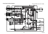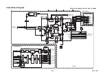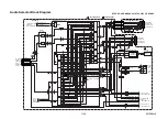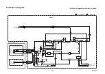
1-11-13
E9TK3TR
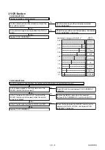
D-FG
D-PG
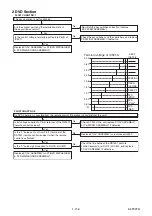
5Vp-p
2.5Vp-p
D-FG
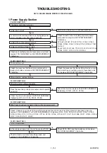
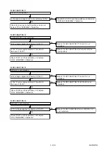
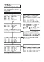
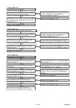
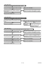
FLOW CHART NO.6
Capstan Motor does not rotate.
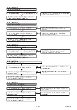
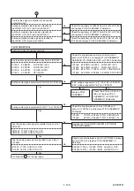
FLOW CHART NO.7
Drum Motor does not rotate.
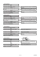
FLOW CHART NO.8
Drum Motor rotates only for a few seconds.
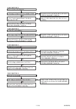
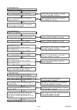
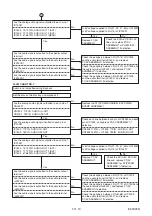
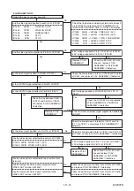
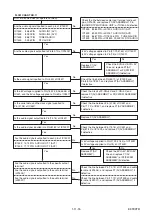
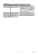
FLOW CHART NO.9
RF-SW signal is not outputted.
Is the Drum Motor rotating?
Is 5V voltage supplied to Pin(2) of CN502?
Is 12V voltage supplied to Pin(1) of CN502?
Is over approximately 2.6V voltage supplied to Pin(5)
of CN502?
Check the P-ON+5V line and replace P1(AV ASSEMBLY)
if defective.
Check the line between Pin(5) of CN502 and Pin(76) of
IC501, and replace P1(AV ASSEMBLY) if defective.
Check AL+16V/+12V line, and replace P1(AV ASSEMBLY)
if defective.
Check the AL+12V line, and replace P1(AV ASSEMBLY)
if defective.
Check the AL+12V line, and replace P1(AV ASSEMBLY)
if defective.
Check the P-ON+5V line and replace P1(AV ASSEMBLY)
if defective.
Check the line between Pin(8) of CN502 and Pin(77) of
IC501, and replace P1(AV ASSEMBLY) if defective.
Replace P1(AV ASSEMBLY).
No
No
No
No
No
No
No
No
No
No
No
Yes
Yes
Yes
Is 5V voltage supplied to Pin(2) of CN502?
Is the D-PFG signal inputted to Pin(90) of IC501?
Is the D-PFG signal inputted to Pin(90) of IC501?
Is 12V voltage supplied at Pin(11) of CN502?
Is the RF-SW signal outputted to Pin(18) of IC501?
Is 12V voltage supplied Pin(11) of CN 502?
Replace DECK ASSEMBLY (1B1).
Replace DECK ASSEMBLY (1B1).
Refer to "FLOW CHART NO.7" <Drum Motor does
not rotate> and "FLOW CHART NO.8" <Drum Motor
rotates only for a few seconds>.
Is over approximately 2.6V voltage supplied to
Pin(8) of CN502?
Yes
Yes
Yes
Yes
Replace P1(AV ASSEMBLY).
Replace DECK ASSEMBLY (1B1).
Yes
Yes
Yes
Yes
Replace DECK ASSEMBLY (1B1).
Replace DECK ASSEMBLY (1B1).
Summary of Contents for DVR19DTKB2
Page 4: ...1 1 1 E9TK3SP SPECIFICATIONS ...
Page 58: ...1 14 3 NOTE BOARD MEANS PRINTED CIRCUIT BOARD E9TK3SCAV1 AV 1 9 Schematic Diagram VCR Section ...
Page 60: ...1 14 5 NOTE BOARD MEANS PRINTED CIRCUIT BOARD E9TK3SCAV3 AV 3 9 Schematic Diagram VCR Section ...
Page 61: ...1 14 6 NOTE BOARD MEANS PRINTED CIRCUIT BOARD E9TK3SCAV4 AV 4 9 Schematic Diagram VCR Section ...
Page 62: ...1 14 7 NOTE BOARD MEANS PRINTED CIRCUIT BOARD E9TK3SCAV5 AV 5 9 Schematic Diagram VCR Section ...
Page 63: ...1 14 8 NOTE BOARD MEANS PRINTED CIRCUIT BOARD E9TK3SCAV6 AV 6 9 Schematic Diagram VCR Section ...
Page 64: ...1 14 9 NOTE BOARD MEANS PRINTED CIRCUIT BOARD E9TK3SCAV7 AV 7 9 Schematic Diagram VCR Section ...
Page 89: ...1 17 3 DVDP_TI Push close 0 08 V 0 02 s Push Close detection Threshold level ...
Page 97: ...1 20 4 E9TK3PEX Packing X 2 X 3 X 6 X1 Upper Side Lower Side FRONT ...
Page 123: ......

