1-9-1
E9TK1FW
FIRMWARE RENEWAL MODE
1. Turn the power on and remove the disc on the tray.
2. To put the DVD recorder & VCR into version up
mode, press [DVD], [INSTANT SKIP], [6], [5], and
[4] buttons on the remote control unit in the order.
Then the tray will open automatically.
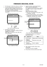
Fig. a appears on the screen and Fig. b appears
on the VFD.
Fig. a Version Up Mode Screen
Fig. b VFD in Version Up Mode
3. Load the disc for version up.
Fig. c appears on the screen. The file on the top is
highlighted as the default.
When there is only one file to exist, Step 4 will
start automatically.
Fig. c Update Disc Screen
4. Select the firmware version pressing arrow
buttons, then press [ENTER/OK].
Fig. d appears on the screen and Fig. e appears
on the VFD. The DVD recorder & VCR starts
updating.
About VFD indication of Fig. e:
1) When Fig. d is displayed on the screen, “F-UP”
is displayed on the VFD.
2) When “Firmware Updating... XX% Complete.”
is displayed on the screen, BE version number
is displayed on the VFD such as 194000.
Fig. d Programming Mode Screen
Fig. e VFD in Version Up Mode (Example)
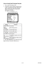
The appearance shown in (*1) of Fig. d is
described as follows.
5. After updating is finished, the tray opens
automatically.
At this time, no button is available.
6. Pull out the AC code once, then insert it again.
* Firmware Version differs depending on the
models, and this indication is one example.
Current
F/W version
is displayed.
Firm Update Mode
Please insert a disc.
ver. *************
* Firmware Version differs depending on the
models, and this indication is one example.
Disc name
is displayed.
Firm Update Mode
ver. *************
VOL_************
************
************
************
************
1 / 1
Files included
in the disc are
displayed.
No.
Appearance
State
1
File Loading...
Sending files into the memory
2
Firmware
Updating...
XX% Complete.
Writing new version data
---
Firmware
Update Failure
Failed in updating
* Firmware Version differs depending on the
models, and this indication is one example.
Firm Update Mode
ver. *************
File Loading...
************
Selected
F/W version
is displayed.
(*1)
Summary of Contents for DVR19DTKB2
Page 4: ...1 1 1 E9TK3SP SPECIFICATIONS ...
Page 58: ...1 14 3 NOTE BOARD MEANS PRINTED CIRCUIT BOARD E9TK3SCAV1 AV 1 9 Schematic Diagram VCR Section ...
Page 60: ...1 14 5 NOTE BOARD MEANS PRINTED CIRCUIT BOARD E9TK3SCAV3 AV 3 9 Schematic Diagram VCR Section ...
Page 61: ...1 14 6 NOTE BOARD MEANS PRINTED CIRCUIT BOARD E9TK3SCAV4 AV 4 9 Schematic Diagram VCR Section ...
Page 62: ...1 14 7 NOTE BOARD MEANS PRINTED CIRCUIT BOARD E9TK3SCAV5 AV 5 9 Schematic Diagram VCR Section ...
Page 63: ...1 14 8 NOTE BOARD MEANS PRINTED CIRCUIT BOARD E9TK3SCAV6 AV 6 9 Schematic Diagram VCR Section ...
Page 64: ...1 14 9 NOTE BOARD MEANS PRINTED CIRCUIT BOARD E9TK3SCAV7 AV 7 9 Schematic Diagram VCR Section ...
Page 89: ...1 17 3 DVDP_TI Push close 0 08 V 0 02 s Push Close detection Threshold level ...
Page 97: ...1 20 4 E9TK3PEX Packing X 2 X 3 X 6 X1 Upper Side Lower Side FRONT ...
Page 123: ......

