background image

3. APPEARANCE  


ENGLISH VERSION 


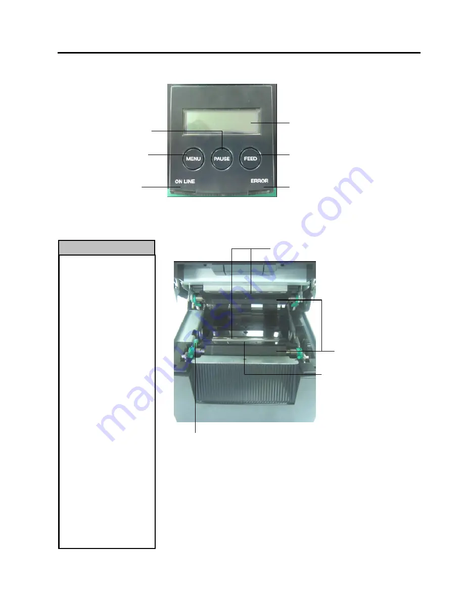
3.4 Operation Panel 


E3-2 


3.4 OPERATION PANEL 


(Refer to Section 4 for further information about the Operation Panel.) 

 
3.5 INTERIOR 


1.


Do not touch the Print Head 
or around it just after 
printing. You may get 
burned as the Print Head 
becomes very hot during 
printing. 

2.


Do not touch any moving 
parts. To reduce the risk of 
fingers, jewellery, clothing, 
etc., being drawn into the 
printer. 

3.


To avoid injury, be careful 
not to trap your fingers 
while opening or closing the 
cover. 

AVERTISSEMENT


1.


Ne touchez pas à la tête 

d'impression ou autour juste 
après l'impression. Vous 
pouvez être brûlé puisque la 
tête d'impression devient très 
chaude pendant  
l'impression.. 

2.


Ne touchez à aucune pièce 

en mouvement. Assurezvous 
d’avoir bien arrêté 
l’imprimante avant de 
charger le média, afin de 
réduire le risque d’avoir vos 
doigts. 

3.


Pour éviter la blessure, 

soyez prudent de ne pas 
coincer vos doigts pendant 
que vous ouvrez ou fermez le 
boîtier. 

WARNING! 


ONLINE LED 
(Blue) 

ERROR LED 
(Orange) 

LCD Message Display 

[

FEED

] Key 


[

MENU

] Key 


[

PAUSE

] Key 

Platen 

Label Gap 
Sensor & Black 
Mark Sensor 

Print Head Element

Sensor Knob 

Summary of Contents for DB-EA4D

Page 1: ...TOSHIBA 2ST LABEL PRINTER DB EA4D SERIES Owner s Manual Mode d emploi Bedienungsanleitung Manual de instrucciones Gebruikershandleiding Manuale Utente Manual do Utilizador ...

Page 2: ...TOSHIBA 2ST LABEL PRINTER DB EA4D SERIES Owner s Manual ...

Page 3: ...lug with wet hands as this may cause electric shock If the machines share the same outlet with any other electrical appliances that consume large amounts of power the voltage will fluctuate widely each time these appliances operate Be sure to provide an exclusive outlet for the machine as this may cause fire or electric shock Do not place metal objects or water filled containers such as flower vas...

Page 4: ...nd ribbons DO NOT STORE the paper or ribbons where they might be exposed to direct sunlight high temperatures high humidity dust or gas Ensure the printer is operated on a level surface Any data stored in the memory of the printer could be lost during a printer fault Try to avoid using this equipment on the same power supply as high voltage equipment or equipment likely to cause mains interference...

Page 5: ...as la fiche secteur avec les mains mouillées Vous risqueriez une électrocution Si la machine partage une même prise avec d autres appareils consommant beaucoup d électricité il y aura des fluctuations de tension importantes lorsque ces appareils fonctionnent Pour éviter tout risque d incendie ou de choc électrique ne branchez pas d autres appareils à la même prise que la machine Ne placez pas d ob...

Page 6: ... que des appareils de forte puissance ou susceptibles d émettre des interférences Eteignez l imprimante lors des interventions à l intérieur ou lors des nettoyages Assurez vous de garder l environnement de travail à l abri de l électricité statique Ne placez pas d objets lourds sur la machine Ils pourraient tomber et blesser quelqu un Ne bouchez pas les ouvertures d aération de la machine La chale...

Page 7: ...th the instruction manual may cause harmful interference to radio communications Operations of this equipment in a residential area is likely to cause harmful interference in which case the user will be required to correct the interference at his own expense for USA only Changes or modifications not expressly approved by manufacturer for compliance could void the user s authority to operate the eq...

Page 8: ...s general household waste By ensuring this product is disposed of correctly you will help prevent potential negative consequences for the environment and human health which could otherwise be caused by inappropriate waste handling of this product For more detailed information about the take back and recycling of this product please contact your supplier where you purchased the product ...

Page 9: ...NS 6 3 APPEARANCE 1 3 1 DIMENSIONS 1 3 2 FRONT VIEW 1 3 3 REAR VIEW 1 3 4 OPERATION PANEL 2 3 5 INTERIOR 2 4 BASIC FUNCTIONS OF OPERATION PANEL 1 4 1 LED INDICATION 1 4 1 1 POWER ONLINE LED 1 4 1 2 ERROR LED 1 4 1 3 INDICATION OF LED AND MEANING 1 4 2 KEYS ON THE NORMAL MODE 1 4 2 1 MENU KEY 1 4 2 2 PAUSE KEY 2 4 2 3 FEED KEY 3 4 3 SPECIAL FUNCTIONS 4 4 3 1 CONFIGURATION PRINT 5 4 3 2 FACTORY DEFA...

Page 10: ...ITH PERFORATION PAPER 16 5 8 PRINTER DRIVER INSTALLATION 17 5 8 1 SYSTEM REQUIREMENT 17 5 8 2 DRIVER INSTALLATION GUIDE BY USING USB PARALLEL 17 5 8 3 DRIVER INSTALLATION GUIDE BY USING LAN 20 5 9 PARAMETER SETTING IN MENU MODE 25 5 9 1 CATEGORY FIRMWARE VERSION CRC 25 5 9 2 CATEGORY COMMUNICATION INTERFACE 25 5 9 3 CATEGORY PRINTER CONFIGURATION 26 5 9 4 CATEGORY PRINTER ADJUSTMENT 29 5 9 5 CATEG...

Page 11: ...GS12 QM R Model name description 1 2 ACCESSORIES When unpacking the printer please check that the following accessories are supplied with the printer Quick Installation Manual Doc No EO1 33092 Safety Precaution Sheet Doc No EO2 33038 Power Cord DB E A 4 D G S 1 0 QM R RoHS Compliant Models Destination Code QM Global Interface Specification 0 USB LAN Interface 2 USB LAN Centronics Interface Printer...

Page 12: ...03 2 dots per inch Printing methods Line thermal printing Direct thermal method Print speeds Max 6 inch sec Dual side printing mode Maximum print width 104mm Dispensing modes Batch mode Continuous Cut mode Available only when cutter module is installed Message display 16 characters x 2 lines Dimensions 240 mm width x 237 mm height x 226 mm depth with Paper hopper 470 mm depth Weight Printer 7 5kg ...

Page 13: ...11 Hole Width Min 12 0 Paper Thickness 0 06 0 22 Maximum Effective length for continuous print 547 8 Maximum Outer Roll Diameter Dia 203 2 8 Roll Direction Outside Label Inner Core Diameter Dia 38 0 42 0 76 2 0 3 NOTE 1 To ensure print quality and print head life use only TOSHIBA TEC specified media 2 When marking black marks on the label rolls they should be marked at the gaps 3 In the case of us...

Page 14: ...a feed direction 1 2 3 4 9 8 5 Effective Printable Area Effective Printable Area Media feed direction 1 8 3 9 11 6 Black Mark Perspective On the back side Perforation Paper with a hole Cut Sheet Paper Rectangular Hole Effective Printable Area Effective Printable Area Media feed direction 1 8 3 9 10 11 Effective Printable Area 3 9 1 8 Media feed direction ...

Page 15: ...ation Paper with a hole Rectangular Holes Label Gap Sensor Sensor position Min 2 0 mm Min 12 mm Magnified view of detection area Detection of hole Rectangular hole Round holes are Unacceptable Media feed direction Label Gap Sensor Sensor position Necessary detection area Label Gap Label Min 3 0 mm Min 12 mm Magnified view of detection area Min 6 0mm when the cutter is used Media feed direction ...

Page 16: ...s movable in the range from 6 0mm to 66 5mm on the left side Tag Paper with black mark Receipt Paper with black mark Label Gap Sensor Detect top of form edge Cut Sheet Media feed direction 6 0mm 66 5mm BM sensor is movable within this range Perspective on the back side Sensor position Center of black mark Min 2 0 mm Min 12 mm Media feed direction ...

Page 17: ... DB EA204 RC QM R A rotary cutter used to repeatedly cut media Paper Roll Holder DB EA904 PH QM R A media roll hanger for media roll with an outer roll diameter up to 203 2mm 8 and inner core diameter up to 76 2mm 3 NOTE To purchase the Optional KIT please contact your authorized TOSHIBA TEC representative or TOSHIBA TEC Head Quarter 13 mm Outside printing area Outside printing area 13 mm 104mm 0 ...

Page 18: ... FRONT VIEW 3 3 REAR VIEW Power Switch O OFF I ON AC Power Inlet USB Interface LAN Interface Parallel Interface Centronics Top Cover Release Button LCD Message Display Top Cover Operation Panel Online LED Error LED Adjustable Paper Guide L R Media Outlet 469 6 With Option Paper Roll Holder 226 237 240 ...

Page 19: ...gers while opening or closing the cover AVERTISSEMENT 1 Ne touchez pas à la tête d impression ou autour juste après l impression Vous pouvez être brûlé puisque la tête d impression devient très chaude pendant l impression 2 Ne touchez à aucune pièce en mouvement Assurezvous d avoir bien arrêté l imprimante avant de charger le média afin de réduire le risque d avoir vos doigts 3 Pour éviter la bles...

Page 20: ...F LED AND MEANING Printer Status Online LED Error LED No Error and No Warning ON OFF Fatal Error ON ON Paper Empty or Cover Open ON Blinks Slowly Normal Error ON Blinks Fast Warning Blinks Slowly OFF IPL Mode Blinks Fast OFF 4 2 KEYS ON THE NORMAL MODE 4 2 1 MENU KEY This key enters Menu Mode 1 Press and hold MENU Key for 3 seconds when the printer is in READY or PAUSE state This key is not activa...

Page 21: ...ce signal are ready to host Mechanical activities are valid On Off PAUSE The printer is in PAUSE state and No error USB Parallel and Ethernet interface signal are ready to host Stops and pauses mechanical activities In READY state or three errors condition LABEL ERROR BM ERROR PERFORATION ERROR if this key is pressed and hold more than 1 sec loaded paper will be parked unloaded to the paper parkin...

Page 22: ... is fed to next BM TOF position If paper is present at Manual cut position Paper is fed to next Manual cut position If paper is present at other position e g just printing is done Paper is fed to next Manual cut position When Rotary cut is set to not OFF Paper is fed to BM TOF position Press FEED Key when Perforation Mode is selected and paper is loaded When Rotary cut is set to OFF If paper is pr...

Page 23: ...s 1 Configuration Print Power On FEED Key 2 Default EEPROM Power On MENU PAUSE FEED Key 3 Menu Mode Power OFF READY Power ON Menu Mode Press and hold MENU key turn on the printer Press and hold MENU key for 3 sec Cofiguration Print Press and hold FEED key turn on the printer Factory Default Press and hold FEED PAUSE FEED key turn on the printer ...

Page 24: ...age appears on the LCD as shown below 2 Press FEED Key shortly it enters Configuration Print Mode and print printer configuration in the same time 3 A message appears on the LCD As shown below 4 Press FEED Key shortly or long After reset printer a message appears on the LCD as shown below Print Config Press FEED Key Printer Config Printing Printer Config Completed NOTE 1 If Cut Sheet mode is selec...

Page 25: ...ned to the default Please see Section 4 3 3 Menu Mode in detail explanation of Category and default setting in Menu Mode Sequence 1 Press and hold MENU PAUSE FEED Key and turn the printer on All I F are in BUSY state during this mode And a message appears on the LCD as shown below 2 Press FEED Key shortly to enter FACTORY DEFAULT 3 After reset printer a message appears on the LCD as shown below Fa...

Page 26: ...enters the Menu Mode b Press MENU Key shortly it exits this mode and shifts to READY state c Press FEED Key long around 3 seconds it exits this mode and shifts to READY state Key function in Menu Mode Key Fuction Shift the next menu downward Increase a value Shift the next menu upward Decrease a value Enter menu Save the setting FEED MENU PAUSE Menu Mode Press FEED Key NOTE Please refer to Appendi...

Page 27: ... Printer Test Modes Sensor Calibration Menu Exit Function selection mode Main Firmware Boot Firmware SBCS CG Return to Prev Layer Menu setting selection mode Black Mark Document Length Label Return to Prev Layer 4 Press PAUSE Key shortly it shifts to the previous selection mode in order as shown below Main menu selection mode Firmware Version CRC Communication Interface Printer Configuration Print...

Page 28: ...the LCD in Menu Mode When exit Menu Mode the printer will be initialized If Accepted is shown on the LCD even once in Menu Mode If Print Printer Configuration is performed in Menu Mode If any Printer Test Modes is performed in Menu Mode or If any Printer Adjustment is performed in Menu Mode FUNCTION OOOOOOOO is a selected function name XXXXXXX is a current setting of a selected function MENU SETTI...

Page 29: ... interface mode in Menu mode Installation Connecting the power cord Sensor Calibration Interface Setting Media sensor position alignment Connecting to a host computer Make a print test in your operating environment and check the print result Print test 5 1 Installation 5 2 Connecting the Power Cord and Cables 5 7 Sensor Calibration 5 3 Setting The Sensor Position 5 2 Connecting the Power Cord and ...

Page 30: ...w NOTE 1 Roll paper holder is required when using roll type media 2 To purchase roll paper holder please contact your authorized TOSHIBA TEC representative or TOSHIBA TEC Head Quarter 3 Refer to the installation manual of roll paper holder upon purchased DB EA904 PH QM R Option WARNING Turn the POWER SWITCH to OFF before installing the roll paper holder unit AVERTISSEMENT Mettez l interrupteur sur...

Page 31: ...he Media Holder Left and Right against the media until it is held firmly in place This will automatically center the media 5 Fold the Release Lever to lock the Media Holder Left Place the Media Holder Unit back to Hopper Unit The Paper Roll Holder Module is ready to be used 6 Set roll paper to roll paper holder as right picture 7 Inset the paper correctly until touching to platen Release Lever Med...

Page 32: ...t radiation and reception of electrical noise the interface cables must meed the following requirements 1 Fully shielded and fitted with metal or metalised connector housings 2 Kept as short as possible 3 Should not be bundled tightly with power cords 4 Should not be tied to power line conduits Power Cord Parallel Interface LAN Interface USB Interface Power Switch Power Switch WARNING Turn the POW...

Page 33: ...e black mark sensor horizontally until the black mark sensor is aligned at the center of black mark on tag paper Black mark sensor is movable within the area of 6 0 66 5mm from the left of tag paper Thermal Head Sensor Knob Black Mark Sensor Label Gap Sensor Sensor position Center of black mark Min 2 0 mm Min 12 mm Black Mark Black Mark Sensor Position WARNING Be careful when handling the print he...

Page 34: ...aper cut sheet paper or perforation paper with rectangular hole using following procedure Open the top cover Rotate the sensor knob to move label gap sensor horizontally until two triangle marks on the sensor cover are aligned Minimum gap dimension between labels are 3 0mm for batch mode and 6 0mm for cut mode Label Gap Sensor Position Sensor Knob Triangle marks are aligned in center ...

Page 35: ...e message is displayed a Press FEED Key shortly it enters the Menu Mode b Press MENU Key shortly it exits this mode and shifts to READY state c Press FEED Key long around 3 seconds it exits this mode and shifts to READY state Key function in Menu Mode Key Function Menu Mode Press FEED Key NOTE Please refer to Appendix II for Menu Mode Tree of this 2ST Printer Power OFF READY Power ON Menu Mode Pre...

Page 36: ...ion menu Of Communication Interface And press FEED key shortly 6 Go to 5 6 Paper Type Setting Parallel Accepted NOTE 1 Press MENU key shortly it shifts the selection mode as arrow 2 Press PAUSE key shortly it shifts the selection mode as arrow 3 Press FEED key shortly Enter menu or save setting value Firmware Version CRC Communication Interface Printer Configuration Printer Adjustment Printer Test...

Page 37: ...lue FEED Shift next address 7 Press FEED key shortly A message appears on the LCD as shown below Ethernet Accepted NOTE 1 Press MENU key shortly it shifts the selection mode as arrow 2 Press PAUSE key shortly it shifts the selection mode as arrow 3 Press FEED key shortly Enter menu or save setting value Interface Type Ethernet Interface Type USB Interface Type USB Default Setting Printer IP Addr 1...

Page 38: ...y in function menu of Communication Interface And press FEED key shortly A message appears on the LCD as shown below 12 Set Subnet Mask A message appears on the LCD as shown below MENU key Increase value PAUSE key Decrease value FEED Shift next address 13 Press FEED key shortly A message appears on the LCD as shown below 14 Select Return to Prev Layer in function menu Of Communication Interface An...

Page 39: ...Return to Prev Layer in function menu Of Printer Configuration And press FEED key shortly 6 Go to 5 7 Sensor Calibration NOTE 1 Press MENU key shortly it shifts the selection mode as arrow 2 Press PAUSE key shortly it shifts the selection mode as arrow 3 Press FEED key shortly Enter menu or save setting value Firmware Version CRC Communication Interface Printer Configuration Printer Adjustment Pri...

Page 40: ...without black mark paper and label paper Calibration with Label Paper It performs sensor calibration with label paper Calibration with Perforation Paper It performs sensor calibration with Perforation paper NOTE If PE sensor detects paper end during this mode paper will be ejected This adjusted value is used for Cut Sheet Mode as well WARNING Be careful when handling the print head as it becomes v...

Page 41: ... with BM paper A message appears on the LCD as shown below 9 Depends on calibration the result a message appears on the LCD as shown below In case of succeeded sensor calibration 10 In case of failed sensor calibration 11 Press and hold FEED Key for three seconds to exit Menu Mode Calibration Performing Calibration Succeeded Failed 12345 x 1 Paper End Sensor 2 Exit Sensor 3 TOF Sensor 4 BM Sensor ...

Page 42: ...e paper A message appears on the LCD as shown below 9 Depends on calibration the result a message appears on the LCD as shown below In case of succeeded sensor calibration 10 In case of failed sensor calibration 11 Press and hold FEED Key for three seconds to exit Menu Mode Calibration Performing Calibration Succeeded Failed 12345 x 1 Paper End Sensor 2 Exit Sensor 3 TOF Sensor 4 BM Sensor 5 Label...

Page 43: ...l paper A message appears on the LCD as shown below 9 Depends on calibration the result a message appears on the LCD as shown below In case of succeeded sensor calibration 10 In case of failed sensor calibration 11 Press and hold FEED Key for three seconds to exit Menu Mode Calibration Performing Calibration Succeeded Failed 12345 x 1 Paper End Sensor 2 Exit Sensor 3 TOF Sensor 4 BM Sensor 5 Label...

Page 44: ...h perforation paper A message appears on the LCD as shown below 9 Depends on calibration the result a message appears on the LCD as shown below In case of succeeded sensor calibration 10 In case of failed sensor calibration 11 Press and hold FEED Key for three seconds to exit Menu Mode Calibration Performing Calibration Succeeded Failed 12345 x 1 Paper End Sensor 2 Exit Sensor 3 TOF Sensor 4 BM Se...

Page 45: ... GUIDE BY USING USB PARALLEL 1 Install by Plug N Play by USB Connect the printer by USB cable when powered on and the windows OS will detect a new hardware then go on 2 3 Hardware Wizard and follow the steps to proceed the installation Install by Plug N Play by Parallel Connect the printer by Parallel cable when powered on and the windows OS will detect a new hardware then go on 2 3 Hardware Wizar...

Page 46: ...atically detect and install my Plug and Play printer Click Next 5 PC will detect new hardware and open Hardware Wizard 6 When the New Hardware Wizard ask whether to connect to Windows Update Select No not this time and click Next 7 Select Install from a list of specific location Advanced and click Next ...

Page 47: ...er in these locations and then tick on Include this location in the search Browse for the printer driver file location and click Next 9 The OS will give windows logo testing warning just ignore and click Continue Anyway 10 After OS copied the driver files into system Click Finish to complete installation ...

Page 48: ...RSION 5 8 Printer Driver Installation E5 20 11 After installation you ll see TOSHIBA DB EA4Din the Printers and Faxes folder 5 8 3 DRIVER INSTALLATION GUIDE BY USING LAN 1 Open Printers and Faxs click Add a Printers 2 Click Next ...

Page 49: ...TER SETUP ENGLISH VERSION 5 8 Printer Driver Installation E5 21 3 Select Local printer attached to this computer and Click Next 4 Select Create a new port and Standard TCP IP Port and click Next 5 Click Next ...

Page 50: ...5 8 Printer Driver Installation E5 22 6 Input printer IP address to Printer Name or IP Adress and click Next 7 Click Finich 8 When the New Hardware Wizard ask whether to connect to Windows Update Select No not this time and click Next ...

Page 51: ... of specific location Advanced and click Next 10 Select Search for the best driver in these locations and then tick on Include this location in the search Browse for the printer driver file location and click Next 11 The OS will give windows logo testing warning just ignore and click Continue Anyway ...

Page 52: ...NGLISH VERSION 5 8 Printer Driver Installation E5 24 12 After OS copied the driver files into system Click Finish to complete installation 13 After installation you ll see TOSHIBA DB EA4Din the Printers and Faxes folder ...

Page 53: ...talled SBCS CG on the second line of the LCD as below vvvvv 5 digits for the version number cccc 4 digits for CRC 5 9 2 CATEGORY COMMUNICATION INTERFACE User can select communication interface function menu in this category Default setting of the function Function List of Menu Description Interface Type USB Ethernet Parallel Select the interface type Note If Parallel option is not installed Parall...

Page 54: ...gth in n 203 inch This length is used as the form length in Document Length and Cut Sheet mode of Paper Type for normal printing Refer to the chapter Document Length Mode Note In Printer Test modes this printer has individual setting of Form Length If this length is smaller than 960 120mm it will be handled as 960 120mm in Cut Sheet mode Print Mode Others Receipt Select a print mode Others Label T...

Page 55: ... Print Speed this setting is valid for the maximum printing speed for Variable Page Recovery Off On Select an error page recovery mode on or off If on is selected the page data which error was occurred is kept and it will be printed on the first page after loading paper BM Cut Offset 59 5 59 Set the BM Black Mark cut offset in 10 203 The origin offset value 0x00 of cut position is the edge of a bl...

Page 56: ... 0 10 50 100 Select the threshold to define Thermal Head Warning or Thermal Head Error If 0 is selected no warning message or errors are indicated even though any failure elements of thermal print head are found at the time of Power ON the printer If any number is selected except 0 the number is used for the threshold to define whether Thermal Head Warning or Thermal Head Error is indicated e g If...

Page 57: ... the actual position which is caused by the fixing sensors position and other factors BM Cut Position 15 0 15 Adjust the cut position in 1 203 This value is valid for the BM mode The purpose of this adjustment is to eliminate the difference between the theoretical position and the actual position which is caused by the fixing sensors position and other factors Label Cut Pos 15 0 15 Adjust the cut ...

Page 58: ...figuration This setting is used in Printer Test modes It is selectable print test functions in this category Refer to the following table This category performs printing tests Function Description Rolling ASCII Simplex It performs Rolling ASCII print on 1ST side Refer to the Chapter Rolling ASCII print test H Print Test Simplex It performs H print on 1ST side Refer to the Chapter H print test Dot ...

Page 59: ...tly 3 Performs a printing test During performing a printing test a message appears on the LCD as shown below e g If you want to stop performing During performing a printing test press FEED Key long then the printer stops printing A message appears on the LCD as shown below e g And then press FEED Key shortly The printer returns to the selection of Menu Mode If detects errors or warnings during per...

Page 60: ...ine mode BM Cut Offset Label Cut Offset Top Margin Label Top Margin BM Cut Position and Label Cut Pos Paper Load 2 H print test This mode performs rolling H print test repeat and page number is printed on the top left corner of the page The print result as follows If the setting of paper type is Black Mark Mode the paper is cut at the next Black Mark w Cutter or fed to the next Black Mark to cut a...

Page 61: ...er or fed to the next Black Mark to cut at manual cut position w o Cutter If the paper type is Document Length Mode the paper is cut at the end of the page w Cutter or fed to the end of the page to cut at manual cut position w o Cutter If the paper type is Label Mode the paper is cut at the next gap w Cutter or fed to the next gap to cut at manual cut position w o Cutter The following settings of ...

Page 62: ...page to cut at manual cut position w o Cutter If the paper type is Label Mode the paper is cut at the next gap w Cutter or fed to the next gap to cut at manual cut position w o Cutter The following setting of Menu Mode is valid in Graphics print test Paper Type Form Length Paper Width Paper Density Power Control Maximum Speed Page Recovery only Online mode BM Cut Offset Label Cut Offset Top Margin...

Page 63: ...fications that exceed Na 800ppm K 250ppm and Cl 500ppm Some ink used on pre printed labels may contain ingredients that can shorten the print head s product life Do not use labels pre printed with ink that contain hard substances such as carbonic calcium CaCO3 and kaolin Al2O3 2SiO2 2H2O For further information please contact your authorized TOSHIBA TEC representative or paper manufacturer CAUTION...

Page 64: ...un solvant organique comme les diluants ou le benzène pour nettoyer L utilisation de pareils solvants pourrait entraîner la décoloration des boîtiers une mauvaise qualité d impression ou la panne de l imprimante 3 Ne touchez pas le composant de la tête d impression l électricité statique accumulée pourra endommager la tête d impression NOTE Please purchase the Print Head Cleaner from the authorize...

Page 65: ...leaning i e low usage weekly high usage daily 1 Turn the power off 2 Open the top cover 3 Remove the paper 4 Clean the print head element with print head cleaner or cotton swab soft cloth slightly moistened with ethyl alcohol 5 Clean the platen with soft cloth moistened with absolute ethyl alcohol 6 Remove dust paper particles or glue from the detection area of the sensors and paper path with a dr...

Page 66: ...O NOT POUR WATER directly onto the printer 2 DO NOT APPLY cleaner or detergent directly onto any cover 3 NEVER USE THINNER OR OTHER VOLATILE SOLVENT on the plastic coverts 4 DO NOT clean the covers with alcohol as it may cause them to discolor loose their shape or develop structural weakness AVERTISSEMENT 1 NE VERSEZ PAS DE L EAU directement sur l imprimante 2 N APPLIQUEZ PAS de nettoyant ou déter...

Page 67: ...pe and specification And perform Sensor Calibration Section 5 4 and 5 7 3 READY LABEL PAGE OVER On Blink fast The print data is over label length which printer measured Adjust print data length within label length ERROR BLACK MARK On Blink fast 1 The printer cannot detect Black Mark 1 Check the media type and black mark specification 2 The black mark sensor is not correctly aligned with black mark...

Page 68: ...ration paper Ceck the media type and perforation paper s specification READY PERFO PAGE OVER On Blink fast The print data is over perforation paper length which the printer measured Adjust the print data length within perforation paper length which the printer measured READY CUT SHEET OVER On Blink fast The print data is over cut sheet length Adjust the print data length within cut sheet length ER...

Page 69: ... The printer is in an error condition 2 Solve the error in the message display The printed image is blurred 1 The print head is not clean 1 Clearn the print head using Section 7 1 2 Print energy is not proper for the media 2 Ajust pint density Section 5 6 3 Dots missing in the print 1 The print head is not clean 1 Clearn the print head Section 7 1 2 Print energy is not proper for the media 2 Ajust...

Page 70: ... with the receive buffer free space information Number of ports 1 Power source Self power Connector Type B Pin No Signal 1 VBUS 2 D 3 D 4 GND Shell Shield LAN Standard IEEE802 23 10Base T 100Base TX Number of ports 1 Connector Magnetic Integrated Connector LAN cable 10BASE T UTP category 3 or category 5 100BASE TX UTP category 5 Cable length Segment length Max 100m Pin No Signal 1 TD 2 TD 3 RD 4 T...

Page 71: ...1 Signal GND 4 DATA2 In 22 Signal GND 5 DATA3 In 23 Signal GND 6 DATA4 In 24 Signal GND 7 DATA5 In 25 Signal GND 8 DATA6 In 26 Signal GND 9 DATA7 In 27 Signal GND 10 nACK Out 28 Signal GND 11 BUSY Out 29 Signal GND 12 PE Out 30 Signal GND 13 SELECT Out 31 nINIT In 14 nAUTOFEED Out 32 nERROR Out 15 NC 33 Signal GND 16 Signal GND 34 NC 17 Chassis GND 35 NC 18 5V DC Out 36 nSELECT IN In Power Connect...

Page 72: ...is not installed Return to Prev Layer this message is not displayed Printer IP Addr xxx xxx xxx xxx Printer IP Address xxx xxx xxx xxx xxx xxx xxx xxx Accepted Subnet Mask xxx xxx xxx xxx Subnet Mask xxx xxx xxx xxx xxx xxx xxx xxx Accepted Default Gateway xxx xxx xxx xxx Default Gateway xxx xxx xxx xxx xxx xxx xxx xxx Accepted Get IP Address xxxxx Get IP Address xxxxx xxxxx Accepted DHCP IP Addre...

Page 73: ...x Socket Port UDP xxxx xxxx Accepted Socket Port UDP2 xxxx Socket Port UDP2 xxxx xxxx Accepted Physical Layer xxx xxx xxx xxx FTP User Name xxxxxxxxxxxxxxxxx Return to Prev Layer Printer Configuration Paper Type xxxxxx Paper Type Black Mark Black Mark Accepted Paper Type Document Length Document Length Accepted Paper Type Label Label Accepted Paper Type Perforation Perforation Accepted Paper Type ...

Page 74: ...sity F xxx Print Density F 15 15 Accepted Print Density F xxx xxx Accepted Print Density F 0 0 Accepted Print Density F xxx xxx Accepted Print Density F 15 15 Accepted Return to Prev Layer Print Density B xxx Print Density B 15 15 Accepted Print Density B xxx xxx Accepted Print Density B 0 0 Accepted Print Density B xxx xxx Accepted Print Density B 15 15 Accepted Return to Prev Layer Power Control...

Page 75: ... Prev Layer Max Variable xxxips Max Variable 6 0ips 6 0ips Accepted Max Variable 5 0ips 5 0ips Accepted Max Variable 4 0ips 4 0ips Accepted Max Variable 3 0ips 3 0ips Accepted Return to Prev Layer Page Recovery xxx Page Recovery Off Off Accepted Page Recovery On On Accepted Return to Prev Layer BM Cut Offset xx BM Cut Offset 59 00 Accepted BM Cut Offset 00 22 Accepted BM Cut Offset 05 29 Accepted ...

Page 76: ...hresh 50 50 Accepted Head Fail Thresh xx xx Accepted Head Fail Thresh 100 100 Accepted Return to Prev Layer Print Printer Config Printer Config Printing Printer Config Completed Return to Prev Layer Printer Adjustment Top Margin xxx Top Margin 15 15 Accepted Top Margin xxx xxx Accepted Top Margin 0 0 Accepted Top Margin xxx xxx Accepted Top Margin 15 15 Accepted Return to Prev Layer Printer Adjust...

Page 77: ... Pos 15 15 Accepted Label Cut Pos xxx xxx Accepted Label Cut Pos 0 0 Accepted Label Cut Pos xxx xxx Accepted Label Cut Pos 15 15 Accepted Return to Prev Layer Perfo Cut Pos xxx Perfo Cut Pos 15 15 Accepted Perfo Cut Pos xxx xxx Accepted Perfo Cut Pos 0 0 Accepted Perfo Cut Pos xxx xxx Accepted Perfo Cut Pos 15 15 Accepted Return to Prev Layer Printer Test Modes Test Mode Configuration Paper Type x...

Page 78: ... H Print Test Simplex H Print Test Printing H Print Test Completed Dot Check Test Simplex Dot Check Test Printing Dot Check Test Completed Graphics Test Simplex Graphics Test Printing Graphics Test Completed Rolling ASCII Duplex Rolling ASCII Printing Rolling ASCII Completed H Print Test Duplex H Print Test Printing H Print Test Completed Dot Check Test Duplex Dot Check Test Printing Dot Check Tes...

Page 79: ...tion Menu setting Acknowledge Result Sensor Calibration Sensor Calibration Calibration with Perforation Pap Calibration Performing Calibration Succeeded Failed 12345 Sensors Return to Prev Layer 1 Paper End Sensor 2 Exit Sensor 3 TOF Sensor 4 BM Sensor 5 Label Sensor No Error x Failure Return to Prev Layer Menu Exit ...

Page 80: ...E EO1 33091A ...

Reviews: