2. PRINTER SETUP
ENGLISH VERSION EO1-33056
2.8 Setting an Operating Environment
E2-48
2.8.7 IP Address Setting
(TCP/IP) (Cont.)
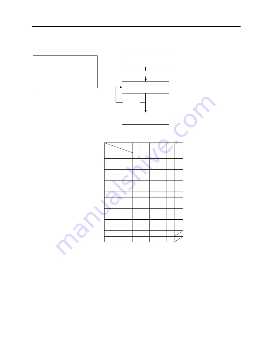
(7) DHCP Host Name
This parameter is to set a DHCP host name.
ASCII code and Hex. code correspondence table
Upper 4 bits
Lower 4 bits
2 3 4 5 6 7
0 SP
0
@
P
`
p
1 !
1
A
Q
a
q
2 “
2
B
R
b
r
3 #
3
C
S
c
s
4 $
4
D
T
d
t
5 %
5
E
U
e
u
6 &
6
F
V
f
v
7 ‘
7
G
W
g
w
8 (
8
H
X
h
x
9
) 9 I Y
i y
A *
:
J
Z
j
z
B
+ ; K
[ k {
C ,
<
L
\
l
|
D -
=
M
]
m
}
E .
>
N
^
n
F /
?
O
_
o
SP = Space
(Example)
To enter “TOSHIBA” in Hex. code:
54 4F 53 48 49 42 41
When the system mode settings have been completed, turn off the printer.
<7>IP ADDRESS
DHCP HOST NAME
MODE ASCII
[PAUSE]
[PAUSE]
<7>IP ADDRESS
Enter a character or a value for each of 1st
byte to 16th byte sequentially using the
[FEED]
or
[RESTART]
key.
NOTE:
After the 16th byte of the DHCP
host name is set, press the
[PAUSE]
key. At this time, the
display will turn to “<7>IP
ADDRESS”.